
Page 83 - 15 Dangerously Mad Projects for the Evil Genius
P. 83
62 15 Dangerously Mad Projects for the Evil Genius
position, make a note of which terminal on the Push all of the components into place and then
motor was positive. use Figure 5-23 as a reference to connect up the
If it just kind of twitches a bit, then try the components. The front of the completed board is
battery the other way around. shown in Figure 5-24, while Figure 5-25 shows the
back of the board.
At this point, you can also experiment with
different weights on the arm to see what works Take particular care to get the phototransistor
best for your motor. the correct way around. Check its data sheet, but
the longer lead is normally the emitter and the
shorter lead the collector. The collector goes to the
Step 4. Add the Electronics
positive 9V supply.
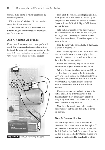
We can now fit the components to the perforated Glue the battery clip perpendicular to the board,
board. The component leads are pushed in from as shown in Figure 5-24.
the top of the board and connected together on the
When connecting wires to the motor, make sure
back of the board using the component leads and
you connect the positive power supply to the
wire. Figure 5-23 shows the wiring diagram.
connection you found to be positive in the test at
the end of the previous section.
We can now test everything before we move
onto the final stage of fitting it all into the can.
While in the can, the phototransistor will be in
very low light, so we need to do this testing in
fairly low light to prevent the phototransistor from
being turned on all the time. We can also turn the
preset variable resistor to its most clockwise
position to make the sensor as insensitive as
possible.
Connect everything up and put the arm in its
resting place. If the motor is activated, then
disconnect the battery immediately and check
everything. Remember, if the motor is left on but is
unable to move, it may burn out.
Now shine the laser (or any light) onto the
phototransistor and the arm should fly up to the
top position.
Step 5. Prepare the Can
The first thing we need to do is consume the
contents of the can and clean it out thoroughly. If
the can contains a food that is not to the liking of
the Evil Genius (dog food, for instance), it can be
fed to a minion since the Evil Genius believes it’s
Figure 5-23 Can jumper wiring diagram a crime to waste food. The can should be of the