
Page 81 - 15 Dangerously Mad Projects for the Evil Genius
P. 81
60 15 Dangerously Mad Projects for the Evil Genius
1 15/16 inch (49mm)
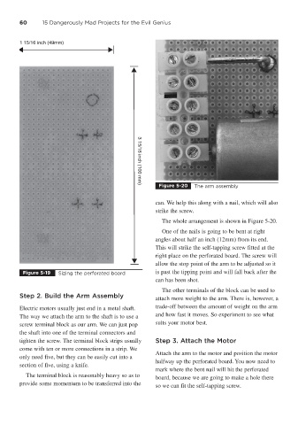
Figure 5-20 The arm assembly
3 15/16 inch (100 mm)
can. We help this along with a nail, which will also
strike the screw.
The whole arrangement is shown in Figure 5-20.
One of the nails is going to be bent at right
angles about half an inch (12mm) from its end.
This will strike the self-tapping screw fitted at the
right place on the perforated board. The screw will
allow the stop point of the arm to be adjusted so it
Figure 5-19 Sizing the perforated board is past the tipping point and will fall back after the
can has been shot.
The other terminals of the block can be used to
Step 2. Build the Arm Assembly attach more weight to the arm. There is, however, a
Electric motors usually just end in a metal shaft. trade-off between the amount of weight on the arm
The way we attach the arm to the shaft is to use a and how fast it moves. So experiment to see what
screw terminal block as our arm. We can just pop suits your motor best.
the shaft into one of the terminal connectors and
tighten the screw. The terminal block strips usually Step 3. Attach the Motor
come with ten or more connections in a strip. We
Attach the arm to the motor and position the motor
only need five, but they can be easily cut into a
halfway up the perforated board. You now need to
section of five, using a knife.
mark where the bent nail will hit the perforated
The terminal block is reasonably heavy so as to board, because we are going to make a hole there
provide some momentum to be transferred into the so we can fit the self-tapping screw.