
Page 76 - 15 Dangerously Mad Projects for the Evil Genius
P. 76
Chapter 5 ■ Balloon-Popping Laser Gun 55
Step 2. Solder the Other
Components
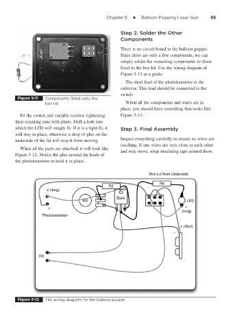
There is no circuit board in the balloon popper.
Since there are only a few components, we can
simply solder the remaining components to those
fixed to the box lid. Use the wiring diagram of
Figure 5-12 as a guide.
The short lead of the phototransistor is the
collector. This lead should be connected to the
switch.
Figure 5-11 Components fitted onto the
box lid When all the components and wires are in
place, you should have something that looks like
Fit the switch and variable resistor, tightening Figure 5-13.
their retaining nuts with pliers. Drill a hole into
which the LED will snugly fit. If it is a tight fit, it Step 3. Final Assembly
will stay in place, otherwise a drop of glue on the
Inspect everything carefully to ensure no wires are
underside of the lid will stop it from moving.
touching. If any wires are very close to each other
When all the parts are attached, it will look like
and may move, wrap insulating tape around them.
Figure 5-11. Notice the glue around the leads of
the phototransistor to hold it in place.
Figure 5-12 The wiring diagram for the balloon popper