
Page 122 - 3D Fibre Reinforced Polymer Composites
P. 122
30 Woven Composites 111
The squashing of warp, weft and z-binder yarns creates regions of high-fibre content in
3D preforms. When the preforms are consolidated, viscous resins can have difficulty
infiltrating these regions that can lead to porosity. 3D woven preforms also have
localised regions of low fibre content, particularly where the in-plane yarns have been
crimped and pushed aside by the z-binders. Upon consolidation these regions become
rich in resin (Farley et al., 1992; Leong et al., 2000).
Z-Binder
Lamii late
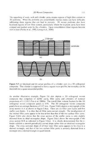
Figure 5.5 (a) Idealised and (b) actual profiles of a z-binder yarn in a 3D orthogonal
composite. The z-binder is supposed to have a square-wave profile, but in reality can be
distorted into a quasi-sinusoidal profile.
As another illustrative example, Figure 5.6 also depicts a 3D orthogonal woven
composite that comprises of stuffer yarns, filler yarns and z-binders of nominal
proportions of 1: 1.2:0.2 (Tan et al, 2000a). The overall fiber volume fraction for the 3D
orthogonal woven composite panels is 43%. The 3D orthogonal woven composite
panels have an average thickness of 2.57 mm. Figure 5.6(b) depicts a micrograph of the
cross section A-A as shown in Figure 5.6(a). There are six filler yarn layers and five
stuffer yarn layers. It is clear that all filler yarns are not straight. The misalignment of
the internal filler yarns appear to be less severe than that of the two surface filler yarns.
Figure 5.6(b) also shows that the cross section of the stuffer yarns is only slightly
distorted from its ideal rectangular shape. Figure 5.6(c) shows the micrograph of the
cross section B-B as indicated in Figure 5.6(a). It is clearly demonstrated that the z-
binder exhibits a smooth periodically curved shape rather than an idealised rectangular
shape. The cross sectional shape of all four inner filler yarns appears to be close to a
skewed rectangle, and that of the two surface filler yarns is severely distorted from a
rectangle into a skewed triangle or quadrilateral.