
Page 126 - 3D Fibre Reinforced Polymer Composites
P. 126
30 Woven Composites 115
comparison between the measured in-plane elastic constants and those predicted using
the block laminate and the unit cell models presented in Chapter 4. In Table 5.1, El and
E2 are the Young’s modulus in the stuffer and filler direction respectively, while vI2 is
the Poisson’s ratio. The experimental results and those predicted using the laminate
block models are detailed in Tan et al (2000a,b). The modulus in the filler yarn
direction is larger than that in the stuffer yarn direction because the fibre content in the
filler yarn direction is 20% more than that in the stuffer yam direction. The predicted
results for the unit cell model are taken from Kim et a1 (2001), who model the full 3D
woven material using an extensive finite element mesh with 108 (27x4~1) unit
structures and total degrees of freedom of 2,671,534. It is shown that the measured in-
plane elastic constants correlate well with those predicted using various model, and the
agreement between the experimental and predicted results are within 10% for all three
in-plane constants.
Table 5.1 Comparison of predicted and measured in-plane elastic constants for 3D
orthogonal woven carbon fibre reinforced composites
Model El (GPa) Ez(GPa) VI2
Analytical Laminate block modela 38.39 50.88 0.034
FEA Laminate Block Modela 39.70 51.09 0.033
FEA Unit Cell Modelb 40.63 49.00 0.037
Average experimental results‘ 40.97 47.30 0.035
a: Tan et a1 (2000b); b: Kim et a1 (2001); c: Tan et a1 (2000a)
0 Experiment Theory
-
30
m
c.
a 25
u)
3
7 20
U
0
2
-
0, l5
.-
v)
C
10
5
0
3D Oflhogonal 3D Normal 3D Offset
Composite Layer Interlock Layer Interlock
Composite Composite
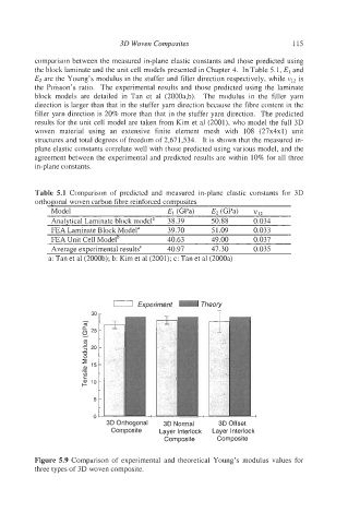
Figure 5.9 Comparison of experimental and theoretical Young’s modulus values for
three types of 3D woven composite.