
Page 236 - A Comprehensive Guide to Solar Energy Systems
P. 236
Chapter 11 • Hybrid Organic–Inorganic Metal Halide Perovskite Solar Cells 239
be achieved [57]. A typical device structure of mesoporous inverted p-i-n consists of
the following arrangement, FTO/compact NiO x /nanocrystal NiO/perovskite/PCBM/
electrode (Fig. 11.3B).
In the mesoporous n-i-p structure, mesoporous and relative conductive TiO 2 or in-
sulating Al 2 O 3 scaffolds are used to facilitate electron transport between the perovskite
absorber and the FTO electrode [19,58]. A complete pore-filling in the mesoporous
structure is important in order to (1) prevent direct leakage of current between two
contacts, (2) increase absorption of photons due to light scattering, and (3) enhance
carrier collection [59]. For the support of light absorption with minimum shunting
pathways, thin perovskite capping layer is always desired on top of the mesoporous
structure. Also, if the mesoporous structure is thicker, the perovskite materials con-
fined within the pores does not have enough space for the sufficient grain growth,
thus ultimately reducing the device performance and lowering the V OC and J SC [60,61].
Therefore, the thickness of mesoporous TiO 2 not only determines the pore filling frac-
tion and perovskite grains but also determines charge transport rate and collection ef-
ficiencies at the perovskite/TiO 2 interface. The development of the n-i-p mesoporous
structure used to fabricate perovskite solar cells has been responsible for the increase
in the solar cell efficiency from 3.8% to over 22%, which has taken place in just 8 years
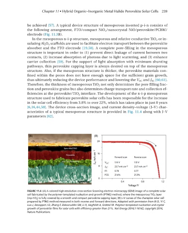
[6,16,44,50]. The device cross-section image, and current density–voltage (J–V) char-
acteristics of a typical mesoporous structure is provided in Fig. 11.4 along with J–V
parameters [62].
FIGURE 11.4 (A) A colored high-resolution cross-section Scanning electron microscopy (SEM) image of a complete solar
cell fabricated by the polymer-templated nucleation and growth (PTNG) method, where the mesoporous TiO 2 layer
(mp-TiO 2 ) is fully covered by a smooth and compact perovskite capping layer, (B) J–V curves of the champion solar cell
prepared by PTNG method measured in both reverse and forward directions. Adapted with permission from Bi D, Yi C,
Luo J, Décoppet J-D, Zhang F, Zakeeruddin SM, Li X, Hagfeldt A, Grätzel M. Polymer-templated nucleation and crystal
growth of perovskite films for solar cells with efficiency greater than 21%. Nat Energy 2016;1:16142, copyright 2016,
Nature Publications.