
Page 235 - A Comprehensive Guide to Solar Energy Systems
P. 235
238 A COMPREHENSIVE GUIdE TO SOLAR ENERGy SySTEMS
communities to perovskite solar cells but also achieved several milestones in device per-
formance using mesoporous structures [23,44,50,53,55]. Mesoporous solar cells require
a high annealing temperature to fabricate TiO 2 films that could be time and energy con-
suming and also costly. As discussed in the Introduction section, MAPbX 3 has a relatively
long charge carrier diffusion length indicating that both electrons and holes can easily
be transported to their electrodes without the need of mesoporous TiO 2 [42]. Therefore,
instead of being limiting to mesoporous structures, researchers started working in planar
device structures. In a planar structure, the perovskite absorber layer is deposited onto a
compact electron transport layer (ETL) instead of depositing onto a mesoporous layer.
By a dual source vapor deposition process, planar perovskite structures achieved an ef-
ficiency of 15.4% in 2013; the present day highest efficiency from this type of structure is
close to 20% [26,56]. In both types of device structures, solar cells can be illuminated either
through ETL layer or the hole transport layer (HTL). If the solar cell is illuminated through
the ETL, the device structure is called an n-i-p structure whereas if the solar cell is illumi-
nated through the HTL, the device structure is called a p-i-n structure.
11.3.1 Mesoporous Scaffold Structure
Mesoporous structures can be divided into two categories depending on which direc-
tion the light incidents on the solar cells. The first use of perovskite solar cell was based
on mesoporous n-i-p structure and is still widely used to fabricate high performance
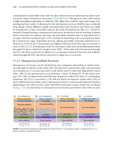
solar cells. In the mesoporous n-i-p structure, a layer of about 50–70 nm thick com-
pact ETL (TiO 2 ) is deposited on the fluorine-doped tin oxide (FTO: SnO 2 :F) coated glass
substrate. The ETL is covered by a 150–300 nm thick mesoporous metal oxide (TiO 2 or
Al 2 O 3 ) filled with perovskite. About 300 nm perovskite is continuously deposited before
depositing a 150–200 nm HTL (spiro-MeOTAd) and back contact metal (Au) as shown
in Fig. 11.3A. An inverted p-i-n mesoporous structure in perovskite solar cells can also
FIGURE 11.3 Schematic diagrams of perovskite solar cells in the (A) n-i-p mesoporous, (B) p-i-n mesoporous (C) n-i-p
planar, and (D) p-i-n planar structures.