
Page 276 - A Comprehensive Guide to Solar Energy Systems
P. 276
280 A COMPrehensIVe GUIDe TO sOlAr enerGy sysTeMs
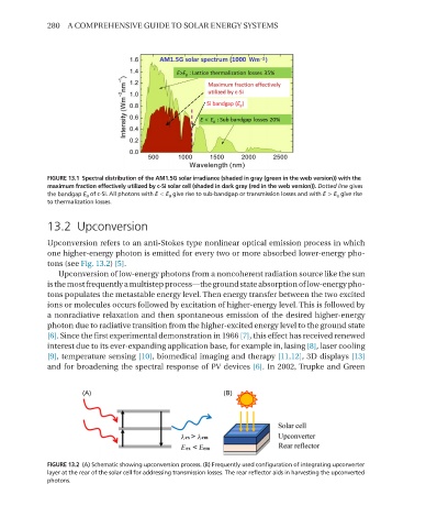
FIGURE 13.1 Spectral distribution of the AM1.5G solar irradiance (shaded in gray (green in the web version)) with the
maximum fraction effectively utilized by c-Si solar cell (shaded in dark gray (red in the web version)). Dotted line gives
the bandgap E g of c-Si. All photons with E < E g give rise to sub-bandgap or transmission losses and with E > E g give rise
to thermalization losses.
13.2 Upconversion
Upconversion refers to an anti-stokes type nonlinear optical emission process in which
one higher-energy photon is emitted for every two or more absorbed lower-energy pho-
tons (see Fig. 13.2) [5].
Upconversion of low-energy photons from a noncoherent radiation source like the sun
is the most frequently a multistep process—the ground state absorption of low-energy pho-
tons populates the metastable energy level. Then energy transfer between the two excited
ions or molecules occurs followed by excitation of higher-energy level. This is followed by
a nonradiative relaxation and then spontaneous emission of the desired higher-energy
photon due to radiative transition from the higher-excited energy level to the ground state
[6]. since the first experimental demonstration in 1966 [7], this effect has received renewed
interest due to its ever-expanding application base, for example in, lasing [8], laser cooling
[9], temperature sensing [10], biomedical imaging and therapy [11,12], 3D displays [13]
and for broadening the spectral response of PV devices [6]. In 2002, Trupke and Green
FIGURE 13.2 (A) Schematic showing upconversion process. (B) Frequently used configuration of integrating upconverter
layer at the rear of the solar cell for addressing transmission losses. The rear reflector aids in harvesting the upconverted
photons.