
Page 201 - A Practical Companion to Reservoir Stimulation
P. 201
PRACTICAL COMPANION TO RESERVOIR STIMULATION
rate. The following expression can be used to calculate the 100 BPM and pressures can vary from a few hundred psi to
expected surface pressure for a treatment: more than 20,000 psi. With this wide range of applications it
is obvious that care must be taken in selecting the proper
pump for a particular treatment. The standard high-pressure
pumps used in well stimulation are single-acting positive
displacement reciprocating pumps (Fig. P-50). These pumps
where WHTP is the wellhead treating pressure, the bottomhole are divided into two sections: the fluid end and the power end.
fracturing pressure is estimated by multiplying a fracture The power end is connected directly to an engineltransmis-
gradient gf by depth H, Apner is the net pressure within the sion power train and converts the rotating power into recipro-
fracture, Aplpipf is the friction pressure drop of the fluid in the cating power. The fluid end is the chamber and plunger of the
tubulars, Apjp..., is the friction pressure drop across the per- pump:.Suction and discharge valves allow fluid flow into and
forations and pH is the hydrostatic pressure. This same calcu- out of the chamber at the beginning and end of each plunger
lation is necessary early in the planning of the well when stroke, respectively. These pumps displace fluid out of the
casing and tubular decisions are being made. chamber only during a forward stroke of the plunger and fluid
The surface pressures of a contained fracture treatment intake on the backstroke. There is no fluid bypass within a
will be the highest at the end of the treatment. Pump rates are pump stroke (positive displacement); therefore, the pump
often limited in an attempt to contain the fracture to a given efficiently moves fluid even under pressure. Most standard
interval. By increasing the pump rate, the net pressure within pumps have three cylinders (triplex pump, Fig. P-5 l), but
the fracture increases and thereby the chances for fracturing some pumps have five cylinders (quintiplex pump, Fig.
through a stress barrier also increase. However, upon exam- P-52).
ining this methodology closely, it can be determined that it is A pumping unit must convert engine horsepower or brake
almost impossible to control the fracture height growth by horsepower into hydraulic horsepower to do the work of a
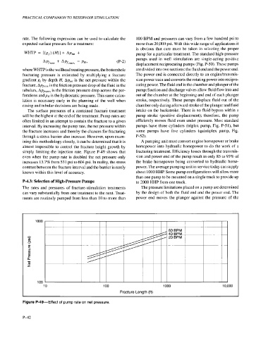
simply limiting the injection rate. Figure P-49 shows that fracturing treatment. Efficiency losses through the transmis-
even when the pump rate is doubled the net pressure only sion and power end of the pump result in only 85 to 95% of
increases 13.7% from 531 psi to 604 psi. In reality, the stress the brake horsepower being converted to hydraulic horse-
contrast between the fracture interval and the barrier is rarely power. The average pumping unit in service today can supply
known within this level of accuracy. about 1000 HHP. Some pump configurations will allow more
than one pump to be mounted on a single truck to provide up
P-4.3: Selection of High-pressure Pumps to 2000 HHP from one truck.
The rates and pressures of fracture-stimulation treatments The pressure limitations placed on a pump are determined
can vary substantially from one treatment to the next. Treat- by the design of both the fluid end and the power end. The
ments are routinely pumped from less than 10 to more than power end moves the plunger against the pressure of the
1000
h
v)
Q
Y
2
3
v)
v)
2
a
c
a
z
100
10 100 1000 10,000
Fracture Length (ft)
Figure P-49-Effect of pump rate on net pressure.
P-42