
Page 203 - A Practical Companion to Reservoir Stimulation
P. 203
PRACTICAL COMPANION TO RESERVOIR STIMULATION
treatment. The total force (lbf) felt by the power end is the rod Maximum
load, RL, of the plunger Rod Plunger klaximum
Number Load Size Pressure
RL = PrdA, (P-3) Plunger (Psi) (in.) (Psi)
where p,d = pressure differential between suction and dis- 3 120,000 21/2 20,000 2.5
charge (psi), andA = cross-sectional area of the plunger (in.*). 3 120,000 3 15,000 4.0
When larger plungers are used in the fluid end portion of 3 120,000 33/4 10,500 6.0
the pump, the rod load against the power end increases for
any given pressure. Therefore, different fluid ends with vari- 3 120,000 4th 7,500 8.5
ous plunger sizes are needed to cover a wide range of treating 3 120,000 5 6,000 10.5
pressures. For a power end with a rod load rating of 200,000 3 120,000 53/4 4,500 14.0
psi, the maximum pressure rating would be 10,185 psi if the .3 120,000 674 3,500 19.0
fluid end had 5-in. plungers. The same power end would have 3 120,000 73/4 2,500 25.0
a pressure rating of 15,915 psi when using a 4-in: plunger. 3 195,000 3Y4 17,000 7.0
The fluid end can be designed to withstand these pressures
regardless of the size of the plunger. Rate is the main limiting 3 195,000 4’/2 12,000 10.0
factor for the fluid end portion of a high-pressure pump. As 3 195,000 5 10,000 12.0
pump speed increases, it becomes increasingly difficult to 3 195,000 5’/2 8,000 14.5
keep the fluid end completely primed on each pump stroke. 3 195,000 6Y4 5,500 22.0
Several factors contribute to inefficiencies as the pump speed 5 160,000 374 15,000 11.0
increases. The fluid frictional forces between the fluid end 5 160,000 4’/2 10,000 16.0
chamber and the valves increase. At the same time, the valve
cycle time, or the time the valves stay open, decreases. Table 5 160,000 5 ’/2 7,000 24.0
P- 11 gives the maximum rates and pressures for several Table P-11-Maximum rate and pressure for various pump
different pump configurations. The maximum rate a pump is configurations.
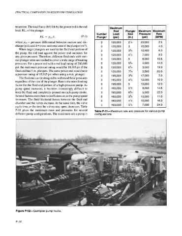
Figure P-52-Quintiplex pump trucks.
P-44