
Page 205 - A Practical Companion to Reservoir Stimulation
P. 205
PRACTICAL COMPANION TO RESERVOIR STIMULATION
tant on continuous-mixed treatments. If the base fluid has not
moved far enough along in the hydration process before the
fluid is crosslinked, the fluid may experience stability prob-
lems.
The organization of tanks and equipment should allow
easy transfer of fluid from storage to the mixing and blending
equipment and then ultimately to the high-pressure pumps.
When the size of the job is large enough to require several
tanks, the tanks should be linked together with a common
manifold. The transfer of fluid is usually done with centrifu-
gal pumps. The hoses or manifolding coming from the tanks
must.be large enough not to impede the flow to the pump. A
good policy is to limit suction hose flow rates to less than
8 ft/sec (8 ft/sec = 8 BPM in a 4-in. hose). If the rate exceeds
8 ft/sec, more hoses should be added.
Proppant storage must also be planned and laid out with
equipment limitations in mind. Most treatments use proppant
storage vessels with bottom conveyor systems to handle
proppant on location (Fig. P-56). These units can generally
move proppant at about 10,000 lb per minute. If treatments
are designed at very high rates or requiring high proppant
concentrations, several of these units may need to operate
simultaneously to maintain the proper addition rate. On very
large jobs a central conveyor system may be required with
multiple storage units feeding it. Some smaller treatments use
hydraulic pumps to haul and add proppants. These units must
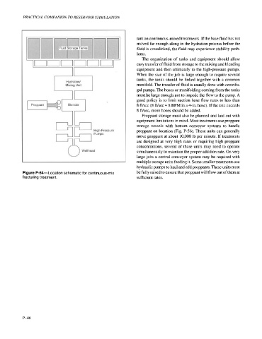
Figure P-54-Location schematic for continuous-mix be fully raised to ensure that proppant will flow out of them at
fracturing treatment. sufficient rates.
P-46