
Page 214 - A Practical Companion to Reservoir Stimulation
P. 214
PRACTICAL CONSIDERATIONS FOR FRACTURE TREATMENT DESIGN
where q; is the rate in BPM, A is area in ft2, k is permeability moved to cover any interval, provided the unperforated cas-
in darcies, Ap is the pressure drop in psi, p is viscosity in cp, ing is sufficient to provide a packer seat. However, caution
and L is the length in ft. Using this expression, 10 ft of 20-40 should be taken when open perforations are present above a
sand in 5%-in. casing will create more than 6000 psi of packer. This leads to the possibility of proppant entering into
pressure drop for a linear gel of 40 cp leaking through the the annular area if the fracture reaches the open perforations.
sand pack at 0.5 BPM. A mixture of sand meshes can be used Very small quantities of proppant on top of a retrievable
ifthe permeability of the sandpack must be reduced to prevent packer can stick the tool string.
flow through the pack.
P-6.2.5: Diversion
P-6.2.3: Frac Bafles At times, diversion is used to control the placement of fluid
Mechanical diversion can also be accomplished by using frac and slurry into the zones of interest. This type of treatment is
baffles. These baffles are run as part of the casing string and advantageous over separately isolating individual zones be-
are placed between individual producing zones. After the cause all treatments can be pumped continually and are
lowest interval is perforated and fractured, a ball is dropped therefore both economical and time efficient. Although ini-
down the casing. This ball seats on the baffle and prevents tially attractive, controlling placement through diversion
fluid flow below this point. The next zone can then be carries many inherent risks.
perforated and fracture stimulated. When multiple zones are The use of bridging materials, such as rock salt and
isolated with baffles, care must be taken to taper the baffle benzoic acid flakes, as the diverting medium will usually
openings. The first ball must be allowed to pass through the result in an overflushed fracture. Some of the bridging material
upper baffles and still seat in the bottom baffle (Fig. P-60). will enter the fracture and displace the near-wellbore proppant
before diversion is achieved at the perforations. Conductivity
P-6.2.4: Bridge Plugs and Packers near the wellbore will be destroyed, resulting in a choked
When completion practices do not allow the progressive fracture with limited production capabilities.
order of fracturing to proceed from the lower zone of interest This problem is pronounced when high-viscosity,
up to higher intervals, bridge plugs must be used in conjunction crosslinked fluids are used for fracturing. These fluids are
with packers. Using a combination of bridge plugs and pack- very efficient at proppant transport and will carry the proppant
ers to straddle an interval provides an extremely reliable away from the perforations as they are displaced by the
method of isolation. These retrievable tools can easily be diverter slurry. The diverter overflush may not be a significant
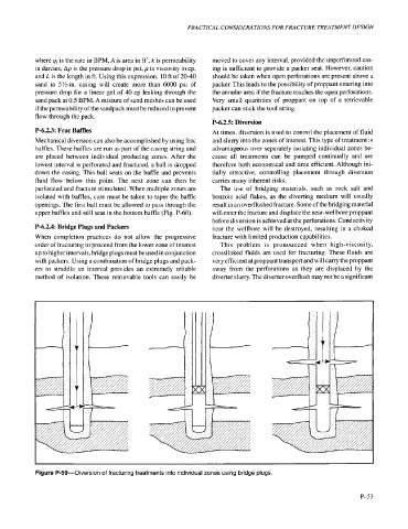
Figure P-59-Diversion of fracturing treatments into individual zones using bridge plugs.
P-53