
Page 219 - A Practical Companion to Reservoir Stimulation
P. 219
PRACTICAL COMPANION TO RESERVOIR STIMULATION
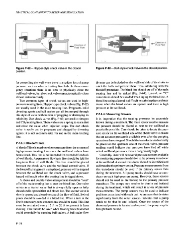
Figure P-62-Flapper-style check valve in the closed Figure P-63-Dart-style check valve in the closed position.
position.
for controlling the well when there is a sudden loss of pump diverter can be included on the wellhead side of the choke to
pressure, such as when a treating line fails. In these emer- catch the balls and prevent them from interfering with the
gency situations there is no time to physically close the bleedoff procedure. The bleed line should tee off of the main
wellhead valves, but the check valve can automatically close treating line and be staked (Fig. P-64). Lateral, or “Y,”
almost instantaneously. connections should be avoided when laying the bleed line. A
Two common types of check valves are used in high- bleed line using a lateral is difficult to stake in place and may
pressure treating lines. Flapper-type check valves (Fig. P-62) move when the bleed valves are opened and there is high
are usually used in the main treating line. Proppants, solid pressure at the wellhead.
diverting agents and ball sealers can all be pumped through
this style of valve without fear of plugging or destroying its P-7.1.4: Measuring Pressure
reliability. Dart check valves (Fig. P-63) are used in nitrogen It is imperative that the treating pressures be accurately
and COz treating lines. These valves use a spring to seat a dart known during a treatment. The main sensor used to measure
and close the valve when injection stops. The dart check the pressure should be placed as near to the wellhead as
valve is easily cut by proppants and plugged by diverting practically possible. Care should be taken to locate the pres-
agents; it is not recommended for use in the main treating sure sensor on the wellhead side of the check valve to ensure
line. that an accurate pressure is available even after the pumping
operations have stopped. Should the transducer inadvertently
P-7.1.3: Bleedoff Lines be placed on the upstream side of the check valve, pressure
A bleedoff line is used to relieve pressure from the system of readings could indicate that pressures have bled off while
high-pressure treating lines once the wellhead valves have actual wellhead pressures remain dangerously high.
been closed. This line is not intended for extended flowback Generally, there will be several pressure sensors available
of well fluids. A permanent flowback line should be laid for for monitoring purposes in addition to the primary transducer
long-term flow of well fluids. This line should be placed at the wellhead. A second transducer should be identified and
between the check valve and the wellhead control valve. If calibrated to the primary sensor. Pressure measurements from
the bleedoff arrangement is misplaced, pressure will be trapped this transducer should be used if the primary sensor fails
between the wellhead and the check valve, and a pressure during the treatment. All pump trucks should have a trans-
hazard will result when the treating line is rigged down. ducer on each high-pressure pump. However, these sensors
A choke and double-valve arrangement should be “teed” should not be used as the backup to the primary pressure
off of the main treating line to start the bleed line. One valve transducer. The pumps may need to be shut in and isolated
serves as a master valve that is always fully open or fully during the treatment, which will result in a loss of pressure
closed and is opened first and closed last. The second valve is measurements. The pump sensors may be used to indicate
slowly opened and closed to control the flow of fluid. Swivel problems associated with each unit. A pressure that deviates
joints should be avoided in a bleed line. When a turn in the significantly from the other sensors indicates that a pump
line is necessary, teed connections should be used. This line needs to be shut in and isolated. Once the source of the
must be restrained every 15 ft to 20 ft to prevent it from abnormal pressure is located and repaired, the pump may be
moving. Care should be taken when flowing back fluids that brought back on line.
could potentially be carrying ball sealers. A ball sealer flow
P-58