
Page 224 - A Practical Companion to Reservoir Stimulation
P. 224
PRACTICAL CONSIDERATIONS FOR FRACTURE TREATMENT DESIGN
minimized. Even with good operators, it takes 3 to 5 min to However, use of this type proppant storage requires consider-
move a dump into place and raise it to allow proppant able preplanning since the units are not mobile once they are
delivery. Excessive movement of proppant dumps increases spotted. Specialized cranes are required to raise these units
the chance of not pumping the proper proppant concentra- into place and to lower them for transportation.
tion. If a treatment is designed with large proppant volumes The conveyored sand bin is the most common unit used to
requiring the movement of the dump trucks during pumping deliver proppants to the blender. These units have several
procedures, other proppant storage equipment should be con- compartments for storing proppant. Each compartment has a
sidered. set of hydraulically controlled doors at the bottom. When
Upright storage silos can hold up to 4000 ft3 of proppant. these doors are opened, proppant falls from the container
These silos rely on gravity to feed the blender and do not onto a conveyor belt that leads to the blender. Storage ca-
require hydraulic power to operate. This type of storage pacity 6f these units ranges between 2500 ft3 and 4000 ft3.
eliminates the need for moving trucks around during most Hydraulically powered conveyors can unload these units at
treatments because of the quantity of proppant they hold. proppant delivery rates approaching 25,000 lb/min. When
Depth Volume Depth Depth Volume Depth Volume Depth
(in.) (bW (in.) (in.) (bbl) (in.) (bW (in.)
1 0.5 26 73.2 51 186.7 76 304.9 101 418.2
2 1.6 27 77.3 52 191.6 77 309.7 102 422.1
3 3.0 28 81.4 53 196.5 78 31 4.6 103 426.0
4 4.6 29 85.5 54 201.4 79 31 9.3 104 429.9
5 6.5 30 89.8 55 206.3 80 324.2 105 433.7
6 8.5 31 94.9 56 21 1.3 81 329.0 106 437.4
7 10.7 32 98.3 57 21 6.2 82 333.7 107 441.1
8 13.0 33 102.7 58 221.2 83 338.4 108 445.2
9 15.6 34 107.1 59 225.1 84 343.1 109 448.0
10 18.2 35 111.5 60 231 .O 85 347.8 110 451.5
11 21 .o 36 1 16.0 61 236.1 86 352.4 111 454.8
12 23.8 37 120.5 62 241 .O 87 347.8 112 458.0
13 26.8 38 125.0 63 244.7 88 361.7 113 461.1
14 29.9 39 129.7 64 246.0 89 366.2 114 464.2
15 33.0 40 134.3 65 250.9 90 370.7 115 467.1
16 36.3 41 138.9 66 255.7 91 375.2 116 469.9
17 39.7 42 143.6 67 260.6 92 379.6 117 472.5
18 43.1 43 148.3 68 265.6 93 384.0 118 475.1
19 46.6 44 153.0 69 270.5 94 388.4 119 477.6
20 50.2 45 157.8 70 275.5 95 392.7 120 479.8
21 53.9 46 162.5 71 280.4 96 397.0 121 482.0
22 57.6 47 167.4 72 285.3 97 401.7 122 484.0
23 61.5 48 172.1 73 290.2 98 406.0 123 485.7
24 65.4 49 177.0 74 295.1 99 41 0.1 124 487.2
25 69.3 50 181.9 75 300.0 100 41 4.2 125 488.5
126 489.2
127.5 489.5
(full)
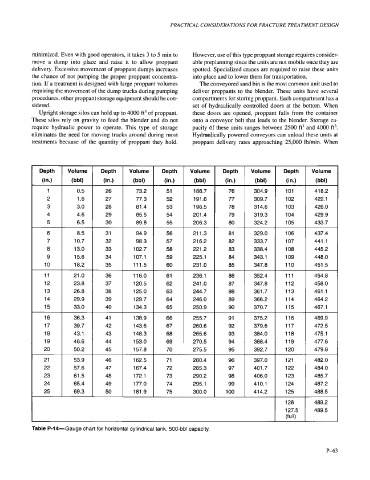
Table P-14-Gauge chart for horizontal cylindrical tank, 500-bbl capacity.
P-63