
Page 220 - A Practical Companion to Reservoir Stimulation
P. 220
PRACTICAL CONSIDERATIONS FOR FRACTURE TREATMENT DESIGN
Master Treating Pipe Maximum Maximum
Rate
Working
High-pressure Valve Nominal ID Pressure
OD
Treating Linel (BPM)
I
Stake
Control
Choke
(Psi)
(in.)
(in.)
1% 1.30 15,000 4.5
2 1.30 20,000 4.5
Stake Every 2 1 .a0 15,000 8.5
20 Ft 2% 2.51 4,000 16.5
I/ Line 3 2.75 15,000 20.0
U 4 3.83 6,000 40.0
5% 5.00 6,500 60.0
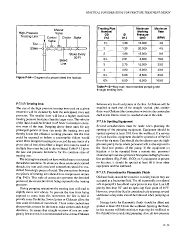
Figure P-64-Diagram of a proper bleed line hookup.
6% 6.00 6,500 100.0
P-7.1.5: Treating Iron between any two fixed points in the line. A Chiksan will be
The size of the high-pressure treating iron used on a given required at each end of the straight section, plus another
treatment will be dictated by both the anticipated rates and three-way Chiksan (the connection swivels in the center plus
pressures. The smaller lines will have a higher maximum each end is free to rotate) is needed at one of the ends.
treating pressure limitation than the larger sizes. The velocity
of the fluid should be limited to 45 ft/sec to minimize exces- P-7.1.6: Spotting Equipment
sive wear of the iron. Pumping above these rates for any Several considerations must be made when planning the
prolonged period of time can erode the treating iron and spotting of the pumping equipment. Equipment should be
thereby lower the effective working pressure that the iron spotted upwind at least 50 ft from the wellhead. If a service
could be exposed to before a catastrophic failure would rig is on location, equipment should be spotted out of the fall
occur. If the designed treating rates exceed the rate limits of a line of the rig mast. Care should also be taken to spot the high-
given size of iron, then either a larger iron must be used or pressure pump trucks where personnel will not be exposed to
multiple lines must be laid to the wellhead. Table P- 12 gives the fluid end portion of the pump. If the equipment on
the rate and pressure limitations for the common sizes of location is to be operated from a remote site, personnel
treating iron. should set up in an area protected from potential high-pressure
The treating iron should not have welded seams or exposed line problems (Fig. P-66). If COZ or N2 equipment is present
threaded connections. To eliminate these seams and exposed on location, it should be spotted at least 60 ft from other
threads, the iron and associated connections should be ma- equipment and the wellhead.
chined from single pieces of metal. The connections between P-7.1.7: Precautions for Flammable Fluids
two pieces of treating iron should have nonpressure unions
(Fig. P-65). This style of connection prevents the threaded Oil-base fluids should be tested for volatility before they are
portion of the connection from being exposed to the treating accepted as a fracturing fluid. The oil is generally considered
pressures. safe to pump if it has a Reid vapor pressure less than 1, an API
During pumping operations the treating iron will tend to gravity less than 50" and an open cup flash point of 10°F.
slightly move and vibrate. To prevent the iron from being However, even if the fluid is considered safe to pump, several
exposed to stress from this movement, the line is laid to additional safety rules should be followed when pumping an
provide some flexibility. Swivel joints or Chiksans allow the oil.
iron some freedom of movement. These same connections Storage tanks for flammable fluids should be diked and
also provide a means for the iron to make comers and change spotted at least 150 ft from the wellhead. Spotting the fluids
directions. To ensure that straight sections of iron are com- in this manner will help minimize exposing the wellhead to
pletely free to move, it is recommended to have three Chiksans fire if problems occur during pumping. Also, all low-pressure
P-59