
Page 227 - A Practical Companion to Reservoir Stimulation
P. 227
PRACTICAL COMPANION TO RESERVOIR STIMULATION
extremely large volumes of proppant are required for a treat- hose should be used to provide fluid to the intake manifold.
ment, conveyored sand bins can be positioned to offload their On low-rate treatments, the hose diameter may have to be
proppant onto a second conveyor that feeds the blender. decreased to maintain a high enough fluid velocity inside the
Spotting sand bins in this arrangement allows millions of hose, especially on high proppant concentration treatments
pounds of proppant to be easily stored and pumped. such as a foam frac. If the pump rate is 5 BPM or less, a 3-in.
Regardless of the type bulk proppant storage used, great hose may be required to prevent proppant from settling out in
care and planning must go into treatments where proppant the hose. If the fluid velocity in a hose drops to a point where
types will be changed during the treatment. Often, several proppant settling is severe, the hose may actually plug off and
different mesh sizes of proppant are used, and it is becoming starve the pump for fluid.
increasingly common to tail in fracture treatments with resin- Each pump truck should have an isolation valve where it is
coated proppants to eliminate proppant flowback. The time tied into the main treating line to allow minor repairs during
and procedures required to change proppant types during the pumping operations. Without this valve the pump would
treatment must be considered in the pretreatment planning. always be exposed to the treating pressure. Behind the isola-
tion valve a bleedoff valve should be present so that the
P-7.4: High-Pressure Pumps pressure on the pump can be safely bled off any time the
High-pressure pumps should be spotted close enough to the pump is brought off line.
blender so that the centifugal pumps of the blender can easily The iron on the pump should be of a size that is compatible
feed slurry at a high enough net positive suction head to the with the rate and pressure capabilities of the pump. If the
intake manifolds on the pumps. On large treatments with pump and iron are not performance matched, the effective
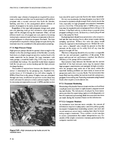
many pumps, a manifold trailer (Fig. P-67) may be used to efficiency of the pump will be minimized.
consolidate the hookup. The manifold trailer helps organize Recirculation lines between the blender and the suction
both the low-pressure suction hookup and the high-pressure manifold of the high-pressure pump may be needed when
discharge hookup. high proppant concentrations are pumped. At high concentra-
The number of suction hoses between the blender and the tions the proppant may settle out of the slurry within this
pumps is determined by the pumping rate. Standard 4-in. manifold. Settling problems are more likely to occur at low
suction hoses of 25-ft length or less will allow roughly 12 pump rates and in low-viscosity fluids. The recirculation line
BPM of fluid flow to the pump. If higher rates are attempted keeps fluid moving within the suction manifold and prevents
through one hose, insufficient net positive suction head may proppant from settling out. Fracturing treatments using foamed
result and cause the pump to cavitate and run roughly. If rates fluids often require a recirculation line.
by one pump are expected to exceed 12 BPM, another suction
P-7.5: Treatment Monitoring
Monitoring of hydraulic fracture treatments has evolved from
simple pressure strip charts to sophisticated computer record-
ing and display. The information displayed by these instru-
ments provides the supervising engineers with diagnostics on
how the treatment is proceeding. Real-time execution decisions
are made during the treatment based on this information.
P-7.5.2: Computer Monitors
As treatments have become more complex, the amount of
information required to adequately control the job has greatly
increased. Computerized monitoring systems can track and
record numerous sensor inputs, making them ideal for moni-
toring complex treatments. These systems can also use data
to create a presentation that makes interpretation easy. Ex-
amples of the simple calculations routinely performed by the
computer monitors are:
Figure P-67-High-pressure pump trucks around the
manifold trailer.
P-66