
Page 28 - A Practical Companion to Reservoir Stimulation
P. 28
RESERVOIR AND WELL CONSIDERATIONS
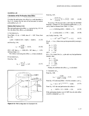
EXAMPLE A-10
From Eq. 1-87,
Calculation of the Perforation Skin Effect
(0.23 12)
Calculate the perforation skin effect for a well described in rpD = ( 1 + F2) = 0.03. (A-28)
Fig. A-12. Assume that the ratio of the horizontal to vertical (2) (0.5)
permeability kH/k, = 5. To use Eq. 1-89, the constants a and b must be calculated
from Eqs. 1-90 and 1-9 1. The correlation coefficients a/, a2, b,
Solution (Ref. Section 1-3.4) and b2 must be obtained from Table 1-3. Thus,
The total perforation skin effect, s,,, is given by Eq. 1-83. At a = (-2.018) log(O.03) + 0.0634 = 3.1, (A-29)
first, the plane-flow effect, q,, is calculated.
A. Calculation of s,, b = (1.6136) (0.03) + 1.7770 = 1.825, (A-30)
From Table 1-2, ae = 0.648, since 8 = 120". Then, from and, finally, from Eq. 1-89,
Eq. 1-85,
s,, = 103.1 1.670.825 0.031.825 = +3.2. (A-3 1)
rk(8) = 0.648 (0.328 + 0.667) = 0.645 ft, (A-25)
If k&,, = 1 (i.e., if there were perfect permeability isotropy),
and from Eq. 1-84, then:
0.328 hD = 0.75,
sjI = In - -0.676. (A-26) r,,D = 0.42,
=
0.645 a = 2.84,
(If 8 = 60°, then sh = - 0.90; if 8 = 90", then sIl = - 0.79. b = 1.84,
All from.Table 1-2.) and s,. = +1.6.
The vertical conveying skin effect, s,,, is then calculated. If h = 2 ft (1 shot/2 ft) (i.e., a job with very bad perforation
density), then:
B. Calculation of s,
From Eq. 1-86, hD = 6.7,
r,,D = 0.0168,
0.5 fi a = 3.64,
hD=-- - 1.67. (A-27) b = 1.804,
0.667 and s, = +12.7.
Finally, the wellbore skin effect, s,,,b, is calculated:
C. Calculation of s,,,,
From Eq. 1-88,
(i( * w - r - 0.328ft 0.328
r,D = = 0.33. (A-32)
0.667 + 0.328
From Eq. 1-92 and using Table 1-4 for the constants c/ and c2,
6.6 10-3e5.320'0.33' -
S,h = - 0.038. (A-33)
From Eq. 1-83, the total perforation skin effect is
s!, = -0.676 + 3.2 + 0.038 = +2.6. (A-34)
If the perforation density were 0.5 SPF, then the skin effect
would be substantial: sI, 3 + 12.
Figure A-1 2-Well configuration for Example A-1 0.
A-I7