
Page 27 - A Practical Companion to Reservoir Stimulation
P. 27
PRACTICAL COMPANION TO RESERVOIR STIMULATION
EXAMPLE A-9
Skin Effect Resulting from (A-24)
Partial Penetration and Slant
From Table 1 - 1 a, the skin effect from partial completion is
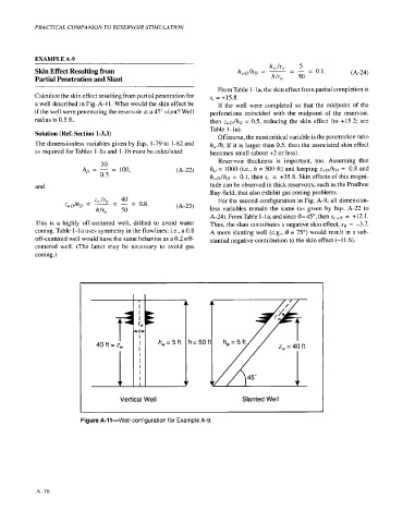
Calculate the skin effect resulting from partial penetration for s, = +15.8.
a well described in Fig. A- 1 1. What would the skin effect be If the well were completed so that the midpoint of the
if the well were penetrating the reservoir at a 45" slant? Well perforations coincided with the midpoint of the reservoir,
radius is 0.5 ft. then zuD/hD = 0.5, reducing the skin effect (to +15.2; see
Table 1-la).
Solution (Ref. Section 1-3.3) Of tourse, the most critical variable is the penetration ratio
The dimensionless variables given by Eqs. 1-79 to 1-82 and hJk If it is larger than 0.5, then the associated skin effect
as required for Tables 1 - 1 a and 1 - 1 b must be calculated: becomes small (about +2 or less).
Reservoir thickness is important, too. Assuming that
50
hi) = - 100, (A-22) hD = 1000 (i.e., h = 500 ft) and keeping zMD/hD 0.8 and
=
=
0.5 h,,D/hD = 0.1, then s, = +35.8. Skin effects of this magni-
and tude can be observed in thick reservoirs. such as the Prudhoe
Bay field, that also exhibit gas coning problems.
For the second configuration in Fig. A-9, all dimension-
(A-23) less variables remain the same (as given by Eqs. A-22 to
A-24).FromTable 1-la,andsince 8=45",then s,+e = +12.1.
This is a highly off-centered well, drilled to avoid water Thus, the slant contributes a negative skin effect, SO = -3.7.
coning. Table 1 - 1 a uses symmetry in the flowlines; i.e., a 0.8 A more slanting well (e.g., 8 = 75") would result in a sub-
off-centered well would have the same behavior as a 0.2 off- stantial negative contribution to the skin effect (-1 1.6).
centered well. (The latter may be necessary to avoid gas
coning.)
40 ft = T h,= 5 ft h= 50 1
Z,
Vertical Well Slanted Well
Figure A-11-Well configuration for Example A-9.
A- I6