Page 112 - A Practical Introduction to Optical Mineralogy
P. 112

SILICATE  MINERALS                                                          PYROXENE  GROUP

                        between  the  high  Ca-bearing  members  (>  25% CaSiO,),  which  are        The  remaining  pyroxenes  of  importance  cannot  be  fitted  into
                        always monoclinic, and the low Ca-bearing members (  < 15% CaSiO,).         Figure 2.20  since  they  include  sodium- and  aluminium-bearing  end
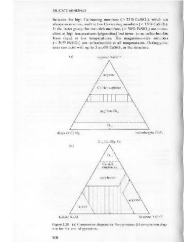
                        In the latter group the iron-rich members (>  30% FeSi0 3 )  are mono-      members. Figure 2.21 shows two further systems to include the Na and
                        clinic at high  temperatures (pigeonites) but invert to an orthorhombic     AI  members.  In  Figure 2.21a  the  central  tie  line  from  Figure 2.20,
                        form  ( opx)  at  low  temperatures.  The  magnesium-rich  members          above  CaMgSiO,-CaFeSi0 3  (50 mol%)  is  used  as  the  base  of  the
                        ( <  30% FeSiO,)  are  orthorhombic at  all  temperatures.  Orthopyrox-     triangle, and the other apex is  NaFe •Si0 3 .  In Figure 2.21b the tie line
                                                                                                                              3
                        enes can exist with  up to 5 mol% CaSiO, in  the structure.                 CaMgSiO,-CaFe •Si0 3 , which represents diopside-hedenbergite or the
                                                                                                                2
                                                                                                    diopside  solid  solution  series  (written  as  diopside,,  or diss),  now  re-
                               (a)         aegirine  NaFc3+                                         presents only one corner of the system, and the Na-bearing pyroxene
                                                                                                    NaFeHSiO,  another.  The  third  apex  of  the  triangle  is  the  phase
                                                                                                    NaAISiO, or jadeite. The main mineral phases occurring are depicted in
                                                                                                    the two figures. The shaded area in Figure 2.21a means that a continu-
                                              aegirine                                              ous  sequence  of change from  diss  to  aegirine  (NaFeHSi0 3 )  does  not
                                                                                                    exist. Similarly it will be observed from Figure 2.21b that the two main
                                                                                                    Al-bearing phases jadeite (NaAISiO,) and omphacite (a cpx containing
                                            Ca-rich aegirine
                                                                                                                    2
                                                                                                    Na,Al,Fe3+ and Mg,Fe •) are both isolated phases, quite separated from
                                                                                                    the other end member in  the system.

                                             aegirine- Di"


                                                Di ,~
                          diopside CaMg                     hedenbergite CaFe
                                            Di"  Ca, Mg, Fe
                               (b)


                                             omphacite


                                   jadeite

                           Jadeite NaAI                       Aegirine NaFe-'+
                                                                                                    Figure  2.22  Extinction  angles  for  clinopyroxenes.  Ranges  of c·y  (maximum
                        Figure 2.21  (a) Composition diagram for Na-pyroxenes (b) composition diag-
                                                                                                    extinction angles) for several common pyroxene minerals. Note that c·a extinc-
                        ram for  Na- and  Al-pyroxenes.
                                                                                                    tion  angles for aegirine/aegirine-augite vary from oo to  - 20°.
                        100
                                                                                                    101
   107   108   109   110   111   112   113   114   115   116   117