
Page 197 - A Practical Introduction to Optical Mineralogy
P. 197
TRANSMITTED-LIGHT CRYSTALLOGRAPHY THE UNIAXIAL INDICATRIX
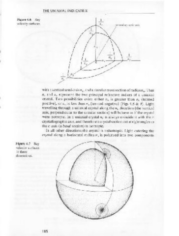
Light travelling through a biaxial crystal in a direction which is per- Figure 4.6 Ray
pendicular to a circular section will behave as if the crystal were iso- velocity surfaces.
tropic. There are two circular sections of the ellipsoid, and therefore /~ ~:_>(secondary optic axis
there must be two perpendiculars along which light will travel resulting
in isotropic sections. These two perpendiculars to the circular sections I I
are called the optic axes (OA) of a crystal, and this explains why the I I \'-
crystal is said to be biaxial. The optic axes lie in the plane of the ellipsoid // / ~~~; \\\
containing then. and n y semi-axes. This plane is called the optic axial
plane (OAP). I I - 1 \ \
The optic axes may be arranged so that either n. or n y bisects the I I 1 O 11 a /1~ \ 7 \ 11 13--
7'
-
smaller of the two angles between them. This smaller angle is called the I 1 /1~ / /
I
optic axial angle or 2V, and the semi-axis which bisects 2V is called I --- ------- //
.....-/
__
the acute bisectrix or Bx •. In Figure 4.3, n y is Bxa since it bisects 2V. The
other semi-axis is called the obtuse bisectrix or Bx 0 • In a positive crystal + t-t~ ----------
n y is Bx., whereas in a negative crystal n. is Bx •. /"
Light is polarised into two components on entering a biaxial crystal,
and these components are shown (for light entering a crystal) along each with a vertical semi-axis n., and a circular cross section of radius n • Thus
0
of the three semi-axes n., np and n y in Figure 4.5. A ray velocity surface n. and n 0 represent the two principal refractive indices of a uniaxial
can be constructed which represents the distance these components will crystal. Two possibilities exist: either n 0 is greater than n 0 (termed
travel in a given time, and this is shown in Figures 4.6 and 4.7. positive), or n. is less than n 0 (termed negative) (Figs 4.8 & 9). Light
travelling through a uniaxial crystal along then. direction (the vertical
axis, perpendicular to the circular section) will behave as if the crystal
were isotropic. In a uniaxial crystal n. is always coincident with the c
4.5 The uniaxial indicatrix
crystallographic axis, and therefore a crystal section cut at right angles to
the c axis (a basal section) is isotropic.
Anisotropic crystals belonging to the tetragonal, trigonal and hexagonal In all other directions the crystal is anisotropic. Light entering the
crystal systems are uniaxial. In a uniaxial indicatrix, which is also an crystal along a horizontal radius n 0 is polarised into two components
ellipsoid, the two horizontal semi-axes (represented by n. and nP in the
biaxial indicatrix) are equal (i.e. n. = n p) and the ellipsoid has a circular Figure 4.7 Ray
cross section. This can be regarded as a limiting case of the biaxial velocity surfaces
indicatrix. Uniaxial crystals are therefore represented by an ellipsoid in three
dimensions.
Figure 4.5
Polarisation in a I
oc-
biaxial crystal. 11~
184 185