
Page 199 - A Practical Introduction to Optical Mineralogy
P. 199
TRANSMITTED-LIGHT CRYSTALLOGRAPHY INTERFERENCE COLOURS AND NEWTON'S SCALE
1 optic axis
Figure 4.8 Positive uniaxial indicatrices. Figure 4.9 Negative uniaxial indicatrices.
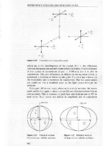
Figure 4.10 Polarisation in a uniaxial crystal.
which vibrate in planes at right angles to each other, with velocities where tln is the birefringence of the crystal, that is, the difference
proportional to 1/n 0 and l in. (Fig. 4.10). Ray velocity surfaces can be between the maximum and minimum refractive indices, tis the thickness
drawn representing the distance that these components will travel in a of the crystal in nanometres (1 JLm = 1000 nm) and A is also in
given time, and these surfaces are shown for positive and negative nanometres. The path difference, as defined in the equation above, is
uniaxial crystals in Figures 4.11 and 4.12. expressed in fractions or whole wavelengths. The value tlnt is known as
the retardation and is expressed in nanometres. The two components
are combined into a resultant wave as the light passes through the
4.6 Interference colours and Newton's Scale analyser.
If the path difference is rnA , where m is a whole number, the waves
Anisotropic crystal grains exhibit colours called interference colours combined by the upper analyser are (m/2)A out of phase (where m is an
when white light passes through them under crossed polars, provided odd number). This is because the polariser and analyser are at 90• to
that an optic axis is not parallel to the microscope axis, in which case the each other. Such waves are similar in amplitude and in opposition
grain behaves as if it were isotropic. Constructive or destructive inter-
ference (i.e. brightness or darkness) of monochromatic light passing : optic axis 1 optic axis
I I ~
through the crystal fragment depends on the path difference between I
the two components, and the orientation of the planes of polarisation of
the crystal in relation to the microscope polariser and analyser. If plane
polarised light of a particular wavelength enters a crystal plate rotated
from an extinction position, the monochromatic light is resolved into
two components vibrating in mutually perpendicular planes (double
refraction). The two components travel with different velocities through
the crystal, and on emergence are not in phase. The path difference
between them depends on the distance travelled through the crystal (i.e.
the thickness of the crystal):
path difference = ~~ Figure 4.11 Principal sections Figure 4.12 Principal sections
of positive ray velocity surfaces. of negative ray velocity surfaces.
186 187