
Page 201 - A Practical Introduction to Optical Mineralogy
P. 201
TRANSMITTED-LIGHT CRYSTALLOGRAPHY INTERFERENCE COLOURS AND NEWTON'S SCALE
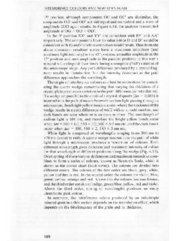
Figure 4.13 15° position, although components OC and OC' are dissimilar, the
Destructive A components OD and OD' are still equal and coincident and a wave of
inferference. amplitude 20D again results. In Figure 4.14, the analyser transmitted
amplitude is OG = OD + OD' .
X In the oo position XX' and YY' are coincident with PP' and AA'
respectively. The components have no value (since D and D' would be
p~~--~~~~~~p·
coincident with 0) and therefore extinction would result. Thus from the
X'
above discussion resultant waves have a maximum amplitude (and
maximum light intensity) in the 45° position, a smaller amplitude in the
15° position and zero amplitude in the parallel position; in this way a
A' mineral will extinguish four times during a complete (360°) rotation of
the microscope stage. Any path difference produced by a crystal frag-
whatever the angular position of the crystal section, and the result is a ment results in illumination, but the intensity decreases as the path
wave of zero amplitude (destructive interference). In Figure 4.13, PP' is difference approaches the wavelength.
the polariser transmission plane, AA' is the analyser transmission plane, The origin of interference colours can best be understood by consid-
XX' and YY' are the two components into which light is resolved on ering the quartz wedge, remembering that varying the thickness of a
passing through the crystal, OBis the amplitude of the wave leaving the crystal plate produces a variation in the path difference (or retardation).
polariser, OC and OC' are the amplitudes of the two components after If a wedge cut parallel to the c axis of a crystal of quartz (<ln = 0.009) is
passing through the crystal plate, and OD and OD' are the amplitudes of inserted into the path of monochromatic sodium light passing through a
these components resolved in the analyser transmission plane. When the microscope, then bright yellow bands are seen where the thickness of the
crystal is in the 4SO position in Figure 4.13, OD and OD' are equal and wedge results in a path difference of m'A/2 with m an odd number, and
opposite and yield a resultant wave of zero amplitude. In the 15° dark bands are seen where m is an even number. The wavelength of
position, although components OC and OC' are dissimilar, OD and sodium light is 580 nm, and therefore the bright yellow bands occur
OD' are equal and opposite and a wave of zero amplitude again results. when <lnt = 580 x 1/2, 580 x 3/2, 580 x 5/2 nm etc., and the dark bands
If m is an odd number, then the components transmitted by the occur when <lnt = 580, 580 x 2, 580 x 3 nm etc.
analyser are in phase and superimposed, so that a maximum resultant White light is composed of wavelengths ranging from 380 nm to
wave is produced with the crystal in the 45° position which has twice the 770 nm (violet to red). A quartz wedge inserted into the path of white
amplitude of either of the interfering waves. The intensity of light of this light through a microscope produces a 'spectrum' of colours. Each
resultant wave is four times as great as the intensity of the light of either different wavelength gives darkness and maximum intensity of colour
wave because intensity is proportional to square of amplitude. This case for that wavelength at different positions along the wedge (Fig. 4.15).
is illustrated in Figure 4.14. In this figure the notation is as before. This Overlapping of these various darknesses and maximum intensities com-
time, however, the components reinforce in the analyser transmission bines to form a series of colours, known as Newton's Scale, which is
plane. In the 45° position in Figure 4.14, OD' and OD are equal and shown in the colour chart (back cover). The colours are divided into
coincident, and therefore analyser transmitted amplitude is 20D. In the different orders. The colours of the first order are black, grey, white,
yellow and finally red. In the second order the colours are violet, blue,
green, yellow, orange and red. Above this the colours become fainter,
A
and the third order consists of indigo, green/blue, yellow, red and violet.
Above the third order, mixing of wavelengths produces an easily
identifiable pink colour.
In summary, the interference colour produced by an anisotropic
mineral grain in a thin section depends on the retardation effect, which
p P' p
depends on the birefringence of the grain and its thickness.
X'
Figure 4.14
Constructive
interference. A' A' Y'
188 189