Page 210 - A Practical Introduction to Optical Mineralogy
P. 210

.J (a)  Direction of insertion NE to SW  (denoted tf)                           '-/(c)  Direction of insertion NE to SW  (denoted  -/  )
             accessory plate:  length slow    length fast                                  accessory plate:  length slow      length fast

           0  0                      1sogyre                                                          a  00
                                        Y yellow  00


                         / ~
          biaxial +ve   o'<-  -ve        Key        +ve          -ve
                                        B blue
                                                                                        biaxial +ve       -ve                    +ve            +ve
                                                                                                                                                    ~
          00                                    B  y         0                           00                                   00
                                    field ofviewD
                                                                                                                ~
                                     ( crosswi res
                                      removed)
          uniaxial  +ve     -ve    isogyre      y   B  +ve       -ve                                         y   B                               B   y
                                                                                        uniaxial  +ve     -ve                    -ve            -ve


          (b)  Direction of insertion NW to SE (denoted"')
            accessory plate:  length slow     length fast

          00~                                 00                                        (d)  Direction of insertion NW  to SE (denoted'>.)   length  fast

                                                                                           accessory plate:  length slow
          '.0
         biaxial  +ve       -ve                    +ve          -ve
          0             'l..B                  ·o o:y                                   biaxial +ve   OAPO
                                                \.
                                                                                                          -ve
                                                              y  B
                         B
                           y
                                                                                        O
         uniaxial +ve       -ve                    +ve           - ve                             y  "QB

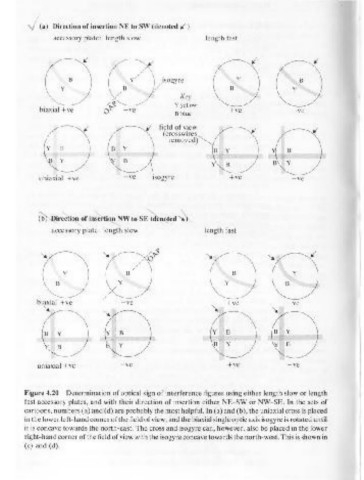
      Figure 4.20  Determination of optical sign of interference figures  using either length slow or length   Y   B   B   Y
      fast  accessory plates, and with  their direction of insertion either NE-SW or NW-SE. In the sets of
                                                                                        uniaxial +ve      - ve                   -ve           -ve
      cartoons, numbers (a) and (d) are probably the most helpful. In (a) and (b), the uniaxial cross is placed
      in the lower left-hand corner of the field of view, and the biaxial single optic axis isogyre is rotated until
      it is concave towards the north-east. The cross and isogyre can, however, also be placed in the lower           '+
                                                                                                             10
       right-hand corner of the field of view with the isogyre concave towards the north-west. This is shown in
      (c)  and  (d).                                                                                   (t-)
   205   206   207   208   209   210   211   212   213   214   215