
Page 213 - A Practical Introduction to Optical Mineralogy
P. 213
TRANSMITTED-LIGHT CRYSTALLOGRAPHY EXTINCTION ANGLE
Figure4.21 All uniaxial and orthorhombic biaxial minerals have straight extinc-
Uniaxial tion - that is, under crossed polars the mineral is in extinction when a
interference prismatic or basal cleavage or prism edge is parallel to one of the
figure. crosswires. Other biaxial minerals possess oblique extinction, although
in some minerals the angular displacement (between, for example,
cleavage and crosswire) may be very small or zero, depending upon the
and then finding a prismatic section which is rotated so that the c axis (or orientation. The angular displacement is called the extinction angle, and
is usually denoted 'Y (slow ray) or a (fast ray) to cleavage.
optic axis) is lying east-west, to get the colour for ne (see Fig. 4.5). The
The mineral section is put into extinction and the character of the two
investigation is done using plane polarised light. The colour related to no
components, which are parallel to the crosswires, noted by rotating each
is termed the o colour and that related to n. termed the e colour.
component into the 45° position and determining whether the compo-
4.9.2 Biaxial minerals nent is fast or slow by using an accessory plate.
In many biaxial minerals a maximum extinction angle will be obtained
The pleochroic scheme for a biaxial crystal requires two differently from a section showing maximum birefringence. Such a section will have
oriented sections. An optic axis normal section which is isotropic under a and 'Yin the plane of the section, and the relationship of one of these
crossed polars will give the colour for n p in plane polarised light. Alter- components to a cleavage or other physical property can be determined.
natively a Bxa figure can be used to find the orientation of n p and the Note that the results of several readings on different grains are not
colour found by rotating np into the east-west position. Remember np is averaged but that the maximum extinction angle is taken. A few biaxial
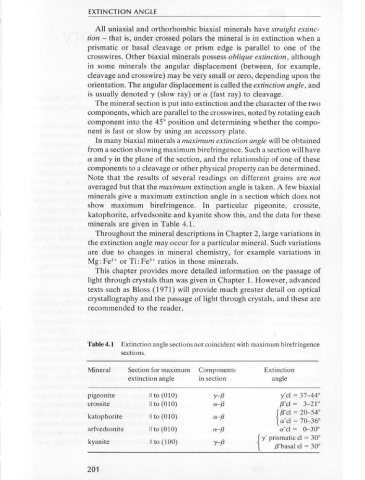
always at right angles to the OAP. Next a section is obtained showing minerals give a maximum extinction angle in a section which does not
maximum birefringence under crossed polars. Such a section should show maximum birefringence. In particular pigeonite, crossite,
have both n. and n, in the plane of section and will have a flash figure as katophorite, arfvedsonite and kyanite show this, and the data for these
its interference figure. The nature of each component has to be deter- minerals are given in Table 4.1.
mined accurately. The fast component has a velocity proportional to Throughout the mineral descriptions in Chapter 2, large variations in
lin. (and is called a), whereas the slow component has a velocity the extinction angle may occur for a particular mineral. Such variations
proportional to lin , (and is called y). Identification is as follows: are due to changes in mineral chemistry, for example variations in
Mg: Fe • or Ti: FeJ+ ratios in those minerals.
2
(1) The section showing maximum birefringence is put into extinction, This chapter provides more detailed information on the passage of
and the two components are now parallel to the polariser and light through crystals than was given in Chapter 1. However, advanced
analyser of the microscope. texts such as Bloss (1971) will provide much greater detail on optical
(2) The section is rotated through 45° so that a length slow first order crystallography and the passage of light through crystals, and these are
red plate can be inserted along one of the components. If addition recommended to the reader.
of retardations occurs and the colour displayed by the mineral
changes to a higher order, then the slow component of the mineral
(i.e. proportional to lin ,) is parallel to the length slow direction of
the plate. If subtraction occurs and the interference colour is Table 4.1 Extinction angle sections not coincident with maximum birefringence
reduced then the fast component (i.e. proportional to lin. ) of the sections.
mineral is in position.
(3) Each component, fast and slow, is rotated in turn into an east-west Mineral Section for maximum Components Extinction
position and the colour noted in plane polarised light to get a and 'Y extinction angle in section angle
respectively.
pigeonite II to (010) y-{3 y' cl = 37-44°
crossite II to (010) a-{3 {J'cl = 3-21°
4.10 Extinction angle
katophorite II to (010) a-{3 {{J'cl = 20-54°
In anisotropic minerals the extinction position is always noted. This is the a'cl = 70-36°
arfvedsonite II to (010) a-{3 a'cl = 0-30°
relationship of some physical property of the mineral- cleavage trace,
{ y· prismatic cl = 30°
face edge, twin plane- to the microscope crosswires when the mineral is kyanite II to (100) y-{3
{3' basal cl = 30°
in extinction.
200 201