
Page 225 - A Practical Introduction to Optical Mineralogy
P. 225
ISOTROPIC AND ANISOTROPIC SECTIONS
REFLECTED-LIGHT THEORY
probably cubic. The mineral could however be non-cubic but with a very
O.Y,---,----,----,---,---,---,---,----,
weak anisotropy. Basal sections of uniaxial minerals are isotropic.
O.X I ......... ~40 5.3.2 Anisotropic sections
Y510
550 Anisotropic sections show colours, known as polarisation or anisotropic
7
0. ~ rotation colours, using crossed polars. The colour effects are usually
560
weak, e.g. dark reddish browns or greys with a bluish tint. Anisotropy is
505 1 ""( best detected by using slightly uncrossed polars, but it must be remem-
~
0.6 570 bered that this may change the polarisation colours. Some of the grains
of a mineral will have a stronger anisotropy than others and some may be
51Kl
0 .5 H-'---t---+---+---t--~k:-:~580 isotropic. Minerals exhibiting anisotropy are usually non-cubic, but
cubic minerals may be distinctly anisotropic (e.g. pyrite).
y
A 590 Using exactly crossed polars, general sections of uniaxial minerals
"' \ . ''"'' ~ have four extinction positions at 90° and identical colours in each 45°
,.+
t-495
0.3 l\
quadrant. Even very slight misalignment of the polarising filters may
with caution in mineral identification. Lower symmetry minerals also
m cov.Ro 1>222t~o- change the colours, and for this reason the colours seen must be used
~
/ 770 show polarisation colours but they need not have distinct extinction
positions nor show the same colours in each 45° quadrant.
-
0.2f-4--,85""\t-+---+--+---+v--f-/~'-------t----1
480\
-
O. l t---47-~~~~,:-60-4-~-~-/---tv-,;;-'"9----+---+---l~--~ 5.3.3 Polarisation colours
Polarisation colours differ in origin from interference colours seen in
thin sections. Their origin can be explained with the help of Figure 5.7,
)L--~~~+7~--~~--~L---~L-----~----~--~
0. I 380 0.2 0.3 0.4 0.5 0.6 0. 7 0.8 which illustrates reflection from a uniaxial transparent mineral, such as
X
calcite, in the 45° orientation. Incident linearly polarised monochro-
matic light, vibrating E-W, is resolved into two components, the two
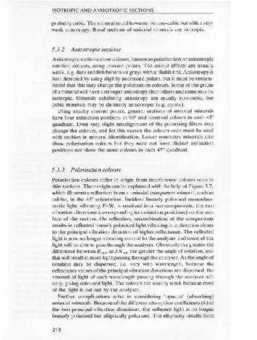
Chromaticity co-ordinates Y%
X y vibration directions (corresponding to extinction positions) on the sur-
0.370 0.370 7.0 face of the section. On reflection, recombination of the components
COY. R 0
sphal. 0.440 0.405 17.0 results in reflected linearly polarised light vibrating in a direction closer
minera l B 0.400 0.385 20.0
to the principal vibration direction of higher reflectance. The reflected
light is now no longer vibrating normal to the analyser and some of the
Figure 5.6 Exercise on use of quantitative colour values: CIE colour diagram
for A source. light will be able to pass through the analyser. Obviously the greater the
difference between Rmax and Rmin the greater the angle of rotation, and
this will result in more light passing through the analyser. As the angle of
5.3 Isotropic and anisotropic sections rotation may be dispersed, i.e. vary with wavelength, because the
reflectance values of the principal vibration directions are dispersed, the
5.3.1 Isotropic sections amount of light of each wavelength passing through the analyser will
vary, giving coloured light. The colours are usually weak because most
Isotropic sections appear dark, ideally black, using crossed polars and of the light is cut out by the analyser.
they should not change in brightness on rotation of the stage. They will
Further complications arise in considering 'opaque' (absorbing)
appear brighter and perhaps coloured if the analyser is slightly rotated,
uniaxial minerals. Because of the different absorption coefficients (k) of
but again there should be no change in the appearance of the section as the two principal vibration directions, the reflected light is no longer
the stage is rotated. If all grains, i.e. small sections in different crystallo-
linearly polarised but elliptically polarised. The ellipticity results from
graphic orientation, of a mineral appear isotropic then the mineral is
212 213