
Page 205 - ARM Based Microcontroller Projects Using MBED
P. 205
8.19 USING THE ANALOG-TO-DIGITAL CONVERTER 191
//
MyPC.printf("\n\rYour Lottery Numbers are : "); // Heading
for(i = 1; i <= LotteryNoCount; i++)
MyPC.printf("%d ", LotteryNumbers[i]); // Numbers
MyPC.printf("\n\rYour Lucky Star Numbers are: "); // Heading
for(i = 1; i <= LuckyStarNoCount; i++)
MyPC.printf("%d ", LuckyStarNumbers[i]); // Numbers
}
}
FIG. 8.52, CONT’D
generated numbers. The main program executes in an endless loop. Inside this loop, the pro-
gram waits until the User button is pressed. The two arrays LotteryNumbers and
LuckyStarNumbers are then cleared to 0. Function Generate is then called to generate the
lottery numbers and the lucky star numbers. Finally, two for loops are used to display the
generated numbers on the PC screen.
Function Generate calls the built-in function rand() to generate random numbers for both
the lottery numbers and the lucky star numbers. The function checks to make sure that the
generated numbers are unique. New numbers are generated if any of the existing numbers
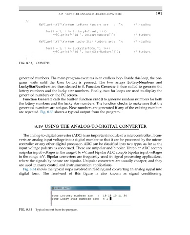
are repeated. Fig. 8.53 shows a typical output from the program.
8.19 USING THE ANALOG-TO-DIGITAL CONVERTER
The analog-to-digital converter (ADC) is an important module of a microcontroller. It con-
verts an analog input voltage into a digital number so that it can be processed by the micro-
controller or any other digital processor. ADC can be classified into two types as far as the
input voltage polarity is concerned. These are unipolar and bipolar. Unipolar ADC accepts
unipolar input voltages in the range 0 to +V, and bipolar ADC accepts bipolar input voltages
in the range V. Bipolar converters are frequently used in signal processing applications,
where the signals by nature are bipolar. Unipolar converters are usually cheaper, and they
are used in many control and instrumentation applications.
Fig. 8.54 shows the typical steps involved in reading and converting an analog signal into
digital form. The front-end of this figure is also known as signal conditioning.
FIG. 8.53 Typical output from the program.