
Page 207 - ARM Based Microcontroller Projects Using MBED
P. 207
8.20 PROJECT 16—DIGITAL VOLTMETER 193
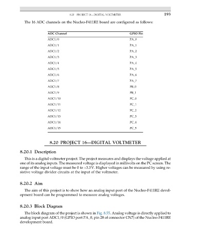
The 16 ADC channels on the Nucleo-F411RE board are configured as follows:
ADC Channel GPIO Pin
ADC1/0 PA_0
ADC1/1 PA_1
ADC1/2 PA_2
ADC1/3 PA_3
ADC1/4 PA_4
ADC1/5 PA_5
ADC1/6 PA_6
ADC1/7 PA_7
ADC1/8 PB_0
ADC1/9 PB_1
ADC1/10 PC_0
ADC1/11 PC_1
ADC1/12 PC_2
ADC1/13 PC_3
ADC1/14 PC_4
ADC1/15 PC_5
8.20 PROJECT 16—DIGITAL VOLTMETER
8.20.1 Description
This is a digital voltmeter project. The project measures and displays the voltage applied at
one of its analog inputs. The measured voltage is displayed in millivolts on the PC screen. The
range of the input voltage must be 0 to +3.3V. Higher voltages can be measured by using re-
sistive voltage divider circuits at the input of the voltmeter.
8.20.2 Aim
The aim of this project is to show how an analog input port of the Nucleo-F411RE devel-
opment board can be programmed to measure analog voltages.
8.20.3 Block Diagram
The block diagram of the project is shown in Fig. 8.55. Analog voltage is directly applied to
analog input port ADC1/0 (GPIO port PA_0, pin 28 of connector CN7) of the Nucleo-F411RE
development board.