
Page 211 - ARM Based Microcontroller Projects Using MBED
P. 211
8.21 PROJECT 17—ANALOG TEMPERATURE SENSOR (DIGITAL THERMOMETER) 197
FIG. 8.59 Block diagram of the project.
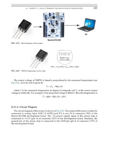
1 2 3
Bottom view
(not to scale)
PIN 1, +V ; PIN 2, V OUT ; PIN 3, GND
S
FIG. 8.60 TMP36 temperature sensor chip.
The output voltage of TMP36 is linearly proportional to the measured temperature (see
Fig. 8.61, curve b) and is given by
T ¼ V o 500ð Þ=10
where T is the measured temperature in degrees Centigrade and V o is the sensor output
voltage in millivolts. For example, if the measured voltage is 800mV, then the temperature is
T ¼ 800 500Þ=10 ¼ 30°C
ð
8.21.4 Circuit Diagram
The circuit diagram of the project is shown in Fig. 8.62. The output of the sensor is directly
connected to analog input ADC1/0 (GPIO port PA_0, pin 28 of connector CN7) of the
Nucleo-F411RE development board. The +Vs power supply input of the sensor chip is
connected to +3.3V (pin 16 of connector CN7) of the development board. Similarly, the
ground pin of the sensor chip is connected to the GND pin (pin 8 of connector CN7) of
the development board.