
Page 216 - ARM Based Microcontroller Projects Using MBED
P. 216
202 8. INTERMEDIATE LEVEL PROJECTS
8.22.3 Block Diagram
The block diagram of the project is as in Fig. 8.59.
8.22.4 Circuit Diagram
The circuit diagram of the project is as in Fig. 8.62. The User LED on the development board
is used to indicate an alarm condition. No other external components are used in the design.
8.22.5 The PDL
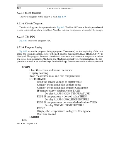
Fig. 8.67 shows the program PDL.
8.22.6 Program Listing
Fig. 8.68 shows the program listing (program: Thermostat). At the beginning of the pro-
gram, the screen is cleared, cursor is homed, and the heading DIGITAL THERMOSTAT is
displayed. The program then reads the desired maximum and minimum temperature values
and stores them in variables MaxTemp and MinTemp, respectively. The remainder of the pro-
gram is executed in an endless loop. Inside this loop, the temperature is read every second
BEGIN
Clear the screen and home the cursor
Display heading
Read the desired max and min temperatures
DO FOREVER
Read the sensor voltage as digital value
Convert the reading into voltage in mV
Convert the reading into degrees Centigrade
IF temperature > desired value THEN
Display ALARM-HIGH TEMPERATURE
ELSE IF temperature < desired value THEN
Display ALARM-LOW_TEMPERATURE
ELSE IF temperatures between desired values THEN
Display NORMAL TEMPERATURE
ENDIF
Display the temperature in degrees Centigrade
Wait one second
ENDDO
END
FIG. 8.67 Program PDL.