
Page 231 - ARM Based Microcontroller Projects Using MBED
P. 231
8.25 PROJECT 21—CHANGING LED FLASHING RATE WITH A POTENTIOMETER 217
8.25.4 Circuit Diagram
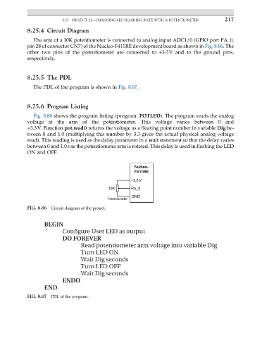
The arm of a 10K potentiometer is connected to analog input ADC1/0 (GPIO port PA_0,
pin 28 of connector CN7) of the Nucleo-F411RE development board as shown in Fig. 8.86. The
other two pins of the potentiometer are connected to +3.3V and to the ground pins,
respectively.
8.25.5 The PDL
The PDL of the program is shown in Fig. 8.87.
8.25.6 Program Listing
Fig. 8.88 shows the program listing (program: POTLED). The program reads the analog
voltage at the arm of the potentiometer. This voltage varies between 0 and
+3.3V. Function pot.read() returns the voltage as a floating point number in variable Dig be-
tween 0 and 1.0 (multiplying this number by 3.3 gives the actual physical analog voltage
read). This reading is used as the delay parameter in a wait statement so that the delay varies
between 0 and 1.0s as the potentiometer arm is rotated. This delay is used in flashing the LED
ON and OFF.
FIG. 8.86 Circuit diagram of the project.
BEGIN
Configure User LED as output
DO FOREVER
Read potentiometer arm voltage into variable Dig
Turn LED ON
Wait Dig seconds
Turn LED OFF
Wait Dig seconds
ENDO
END
FIG. 8.87 PDL of the program.