
Page 233 - ARM Based Microcontroller Projects Using MBED
P. 233
8.26 PROJECT 22—SOUND LEVEL METER 219
8.26.3 Block Diagram
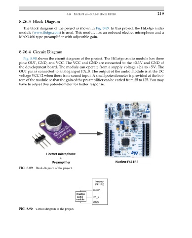
The block diagram of the project is shown in Fig. 8.89. In this project, the HiLetgo audio
module (www.iletgo.com) is used. This module has an onboard electret microphone and a
MAX4466-type preamplifier with adjustable gain.
8.26.4 Circuit Diagram
Fig. 8.90 shows the circuit diagram of the project. The HiLetgo audio module has three
pins: OUT, GND, and VCC. The VCC and GND are connected to the +3.3V and GND of
the development board. The module can operate from a supply voltage +2.4 to +5V. The
OUT pin is connected to analog input PA_0. The output of the audio module is at the DC
voltage VCC/2 when there is no sound input. A small potentiometer is provided at the bot-
tom of the module so that the gain of the preamplifier can be varied from 25 to 125. You may
have to adjust this potentiometer for better response.
FIG. 8.89 Block diagram of the project.
FIG. 8.90 Circuit diagram of the project.