
Page 235 - ARM Based Microcontroller Projects Using MBED
P. 235
8.27 USING THE DIGITAL-TO-ANALOG CONVERTER 221
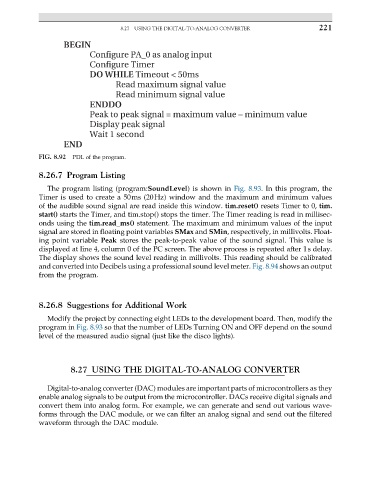
BEGIN
Configure PA_0 as analog input
Configure Timer
DO WHILE Timeout < 50ms
Read maximum signal value
Read minimum signal value
ENDDO
Peak to peak signal = maximum value – minimum value
Display peak signal
Wait 1 second
END
FIG. 8.92 PDL of the program.
8.26.7 Program Listing
The program listing (program:SoundLevel) is shown in Fig. 8.93. In this program, the
Timer is used to create a 50ms (20Hz) window and the maximum and minimum values
of the audible sound signal are read inside this window. tim.reset() resets Timer to 0, tim.
start() starts the Timer, and tim.stop() stops the timer. The Timer reading is read in millisec-
onds using the tim.read_ms() statement. The maximum and minimum values of the input
signal are stored in floating point variables SMax and SMin, respectively, in millivolts. Float-
ing point variable Peak stores the peak-to-peak value of the sound signal. This value is
displayed at line 4, column 0 of the PC screen. The above process is repeated after 1s delay.
The display shows the sound level reading in millivolts. This reading should be calibrated
and converted into Decibels using a professional sound level meter. Fig. 8.94 shows an output
from the program.
8.26.8 Suggestions for Additional Work
Modify the project by connecting eight LEDs to the development board. Then, modify the
program in Fig. 8.93 so that the number of LEDs Turning ON and OFF depend on the sound
level of the measured audio signal (just like the disco lights).
8.27 USING THE DIGITAL-TO-ANALOG CONVERTER
Digital-to-analog converter (DAC) modules are important parts of microcontrollers as they
enable analog signals to be output from the microcontroller. DACs receive digital signals and
convert them into analog form. For example, we can generate and send out various wave-
forms through the DAC module, or we can filter an analog signal and send out the filtered
waveform through the DAC module.