
Page 237 - ARM Based Microcontroller Projects Using MBED
P. 237
8.27 USING THE DIGITAL-TO-ANALOG CONVERTER 223
{
tim.reset(); // Reset Timer
tim.start(); // Start Timer
SMax = 0.0;
SMin = 3300.0;
while(tim.read_ms() < 50) // Do for 50ms
{
mV = 3300.0f * Sound.read(); // In mV
if(mV > SMax) // Find Max
SMax = mV;
else if(mV < SMin) // Find Min
SMin = mV;
}
Peak = SMax - SMin; // Peak-to-peak
tim.stop(); // Stop Timer
clrscr(); // Clear screen
gotoscr('4', '0'); // Line 4, col 0
MyPC.printf("Sound Level = %5.2f", Peak); // Display
wait(1.0); // Wait 1 second
}
}
FIG. 8.93, CONT’D
Just like the ADCs, the resolution of a DAC depends on the number of bits used in the con-
version process. Also, as with the ADCs, DACs also have reference voltages and the output
analog voltage depends on the value of this reference voltage. For example, with a 12-bit (4096
steps) DAC and with a reference voltage of +3.3V, each DAC step corresponds to
3300/4096¼0.805mV. Thus, for example, the 12-bit digital value of “1011 0000 1111” (i.e.,
decimal 2831) corresponds to 2831 0.805¼2.278V.
The STM32F411RET6 processor on the Nucleo-F411RE development board has no built-
in DAC modules. Most other Nucleo boards, however, have one or more DAC modules. For
example, the Nucleo-L476RG development board has two built-in DAC modules. Because the
DAC is an important part of a microcontroller, we shall see in this section how to use a DAC
module by programming the Nucleo-L476RG board using Mbed.
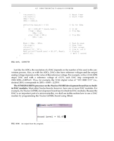
FIG. 8.94 An output from the program.