
Page 80 - ARM Based Microcontroller Projects Using MBED
P. 80
66 6. ARCHITECTURE OF THE STM32F411RET6 MICROCONTROLLER
6.2.1 Power Modes
By default, the microcontroller starts in Run mode after power-up or reset. The microcon-
troller can be configured to operate in one of the following low-power modes.
Sleep Mode
In Sleep mode, the CPU is stopped, all peripherals continue to operate and can wake up the
CPU when an interrupt/event occurs.
Stop Mode
The Stop mode achieves the lowest power consumption while retaining the contents of
SRAM and registers. All clocks in the 1.2V domain are stopped, the phase-locked loop
(PLL), the HSI RC, and the high-speed external (HSE) crystal oscillators are disabled. The
voltage regulator can also be put either in normal or in low-power mode.
Standby Mode
The Standby mode is used to achieve the lowest power consumption. The internal voltage
regulator is switched off so that the entire 1.2V domain is powered off. The PLL, the HSI RC,
and the HSE crystal oscillators are also switched off. After entering the Standby mode, the
SRAM and register contents are lost except for registers in the backup domain when selected.
The devices exit the Standby mode when an external reset (NRST pin), an IWDG reset, a rising
edge on the WKUP pin, or an RTC alarm/wakeup/tamper/time stamp event occurs.
6.2.2 Electrical Characteristics
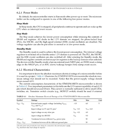
It is important to know the absolute maximum electrical ratings of a microcontroller before
it is used in a project. Table 6.1 illustrates the STM32F411RET6 microcontroller absolute max-
imum ratings that should not be exceeded. Notice that the power-supply voltage should
never exceed 4.0V.
The current consumption characteristic of the STM32F411RET6 microcontroller is shown
in Table 6.2. Two important parameters in this table are the I/O current capability of each I/O
pin which should not exceed 20mA. This current is normally sufficient to drive small LEDs,
switches, etc. Transistor switch circuits (e.g., MOSFET switch) should be used if external
TABLE 6.1 Absolute Maximum Electrical Ratings of the STM32F411RET6 Microcontroller
Symbol Ratings Min Max Unit
External main supply voltage (including V DDA , 0.3 4.0 V
V DD V SS
V DD , and V BAT ) a
V IN Input voltage on FT and TC pins b V SS 0.3 V DD +4.0
Input voltage on any other pin V SS 0.3 4.0
Input voltage for BOOT0 V SS 9.0
jΔV DDx j Variations between different V DD power pins – 50 mV
jV SSX V SS j Variations between all the different ground pins – 50
a
All main power and ground pins must always be connected to the external power supply.
b
V IN maximum value must always be respected.