
Page 76 - ARM Based Microcontroller Projects Using MBED
P. 76
62 6. ARCHITECTURE OF THE STM32F411RET6 MICROCONTROLLER
• 100μA/MHz run time power consumption
• 16-Stream direct memory access (DMA) controllers
• 11 Timers
• Serial wire debug (SWD) and JTAG interface
• 52 I/O ports
•3 I2C interface
•3 USART
•5 SPI/I2S
• SD/MMC/eMMC interface
• Real-time clock (RTC) with hardware calendar
• Cyclic redundancy check (CRC) calculation unit
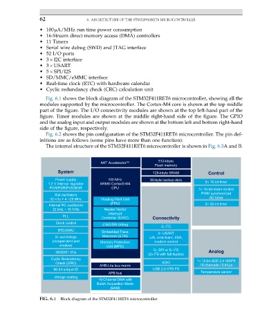
Fig. 6.1 shows the block diagram of the STM32F411RET6 microcontroller, showing all the
modules supported by the microcontroller. The Cortex-M4 core is shown at the top middle
part of the figure. The I/O connectivity modules are shown at the top left-hand part of the
figure. Timer modules are shown at the middle right-hand side of the figure. The GPIO
and the analog input and output modules are shown at the bottom left and bottom right-hand
side of the figure, respectively.
Fig. 6.2 shows the pin configuration of the STM32F411RET6 microcontroller. The pin def-
initions are as follows (some pins have more than one function):
The internal structure of the STM32F411RET6 microcontroller is shown in Fig. 6.3A and B.
512-kbyte
ART Accelerator™
Flash memory
System 128-kbyte SRAM Control
Power supply 100 MHz 80-byte backup data
1.2 V internal regulator ARM® Cortex®-M4 5× 16-bit timer
POR/PDR/PVD/BOR CPU 1× 16-bit motor control
PWM synchronized
Xtal oscillators
32 kHz + 4 ~26 MHz Floating Point Unit AC timer
(FPU) 2× 32-bit timer
Internal RC oscillators
32 kHz + 16 MHz Nested Vector
Interrupt
PLL
Controller (NVIC) Connectivity
Clock control
JTAG/SW debug
2
3× I C
RTC/AWU
Embedded Trace 3× USART
2× watchdogs Macrocell (ETM) LIN, smartcard, IrDA,
(independent and Memory Protection modem control
window) Unit (MPU)
2
5× SPI or 5× I S
36/50/81 I/Os Analog
2
(2× I S with full duplex)
Cyclic Redundancy 1× 12-bit ADC 2.4 MSPS
Check (CRC) SDIO
AHB-Lite bus matrix 16 channels / 0.41μs
96-bit unique ID USB 2.0 OTG FS
APB bus Temperature sensor
Voltage scaling
16-Channel DMA with
Batch Acquisition Mode
(BAM)
FIG. 6.1 Block diagram of the STM32F411RET6 microcontroller.