
Page 73 - ARM Based Microcontroller Projects Using MBED
P. 73
5.2 THE NUCLEO-F411RE DEVELOPMENT BOARD 59
NUCLEO-F411RE
CN7 CN6 CN5 CN10
PC9
PC10 1 2 PC11 1 2 PC8
PC12 3 4 PD2 D15 PB8 10 34 PC6
VDD 5 6 E5V D14 PB9 9 5 6 PC5
AVDD AVDD 8
BOOT0 7 8 GND 7 8 U5V
GND GND 7
NC 9 10 1 NC NC 9 10 NC
NC 11 12 2 IOREF IOREF D13 PA5 6 11 12 PA12
PA13 13 14 3 RESET RESET D12 PA6 5 13 14 PA11
PA14 15 16 4 +3V3 +3V3 D11 PA7 4 15 16 PB12
PA15 17 18 5 +5V +5V D10 PB6 3 2 17 18 NC
GND 19 20 6 GND GND D9 PC7 1 19 20 GND
PB7 21 22 7 GND GND D8 PA9 21 22 PB2
PC13 23 24 8 VIN VIN D7 PA8 8 23 24 PB1
PC14 25 26 NC D6 PB10 7 25 26 PB15
PC15 27 28 1 PA0 A0 D5 PB4 6 27 28 PB14
PH0 29 30 2 PA1 A1 D4 PB5 5 29 30 PB13
PH1 31 32 3 PA4 A2 D3 PB3 4 31 32 AGND
VBAT 33 34 4 PB0 A3 D2 PA10 3 33 34 PC4
PC2 35 36 5 PC1 A4 D1 PA2 2 35 36 NC
PC3 37 38 6 PC0 A5 D0 PA3 1 37 38 NC
CN8 CN9
Arduino Morpho
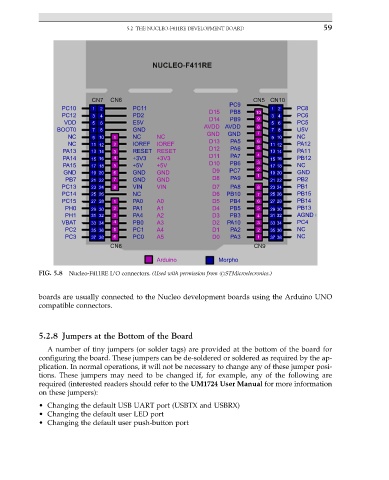
FIG. 5.8 Nucleo-F411RE I/O connectors. (Used with permission from #STMicroelecronics.)
boards are usually connected to the Nucleo development boards using the Arduino UNO
compatible connectors.
5.2.8 Jumpers at the Bottom of the Board
A number of tiny jumpers (or solder tags) are provided at the bottom of the board for
configuring the board. These jumpers can be de-soldered or soldered as required by the ap-
plication. In normal operations, it will not be necessary to change any of these jumper posi-
tions. These jumpers may need to be changed if, for example, any of the following are
required (interested readers should refer to the UM1724 User Manual for more information
on these jumpers):
• Changing the default USB UART port (USBTX and USBRX)
• Changing the default user LED port
• Changing the default user push-button port