
Page 70 - ARM Based Microcontroller Projects Using MBED
P. 70
56 5. THE NUCLEO-F411RE DEVELOPMENT BOARD
E5V U5V
3 2 1
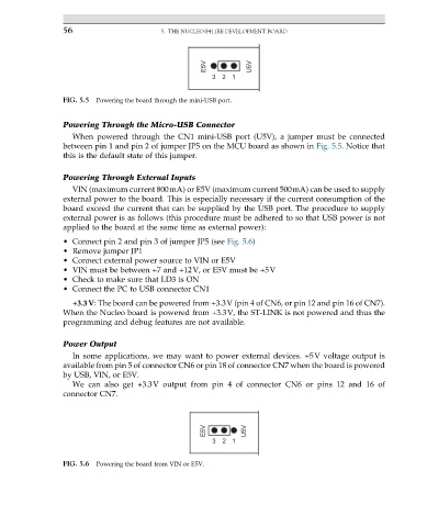
FIG. 5.5 Powering the board through the mini-USB port.
Powering Through the Micro-USB Connector
When powered through the CN1 mini-USB port (U5V), a jumper must be connected
between pin 1 and pin 2 of jumper JP5 on the MCU board as shown in Fig. 5.5. Notice that
this is the default state of this jumper.
Powering Through External Inputs
VIN (maximum current 800mA) or E5V (maximum current 500mA) can be used to supply
external power to the board. This is especially necessary if the current consumption of the
board exceed the current that can be supplied by the USB port. The procedure to supply
external power is as follows (this procedure must be adhered to so that USB power is not
applied to the board at the same time as external power):
• Connect pin 2 and pin 3 of jumper JP5 (see Fig. 5.6)
• Remove jumper JP1
• Connect external power source to VIN or E5V
• VIN must be between +7 and +12V, or E5V must be +5V
• Check to make sure that LD3 is ON
• Connect the PC to USB connector CN1
+3.3V: The board can be powered from +3.3V (pin 4 of CN6, or pin 12 and pin 16 of CN7).
When the Nucleo board is powered from +3.3V, the ST-LINK is not powered and thus the
programming and debug features are not available.
Power Output
In some applications, we may want to power external devices. +5V voltage output is
available from pin 5 of connector CN6 or pin 18 of connector CN7 when the board is powered
by USB, VIN, or E5V.
We can also get +3.3V output from pin 4 of connector CN6 or pins 12 and 16 of
connector CN7.
E5V U5V
3 2 1
FIG. 5.6 Powering the board from VIN or E5V.