
Page 72 - ARM Based Microcontroller Projects Using MBED
P. 72
58 5. THE NUCLEO-F411RE DEVELOPMENT BOARD
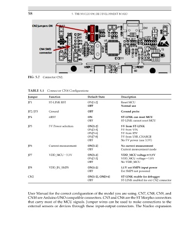
FIG. 5.7 Connector CN2.
TABLE 5.1 Connector CN4 Configurations
Jumper Function Default State Description
JP1 ST-LINK RST ON[1-2] Reset MCU
OFF Normal use
JP2/JP3 Ground OFF Ground probe
JP4 nRST ON ST-LINK can reset MCU
OFF ST-LINK cannot reset MCU
JP5 5V Power selection ON[1-2] 5V from ST-LINK
ON[3-4] 5V from VIN
ON[5-6] 5V from E5V
ON[7-8] 5V from USB_CHARGE
OFF No 5V power (use 3.3V)
JP6 Current measurement ON[1-2] No current measurement
OFF Current measurement mode
JP7 VDD_MCU¼3.3V ON[1-2] VDD_MCU voltage53.3V
ON[2-3] VDD_MCU voltage¼1.8V
OFF No VDD_MCU
JP8 VDD_IN_SMPS ON[1-2] 1.1V ext SMPS input power
OFF Ext SMPS not powered
CN2 ON[1-2], ON[3-4] ST-LINK enable for debugger
OFF ST-LINK enabled for ext CN2 connector
User Manual for the correct configuration of the model you are using. CN7, CN8, CN9, and
CN10 are Arduino UNO compatible connectors. CN5 and CN6 are the ST Morpho connectors
that carry most of the MCU signals. Jumper wires can be used to make connections to the
external sensors or devices through these input-output connectors. The Nucleo expansion