
Page 66 - ARM Based Microcontroller Projects Using MBED
P. 66
52 5. THE NUCLEO-F411RE DEVELOPMENT BOARD
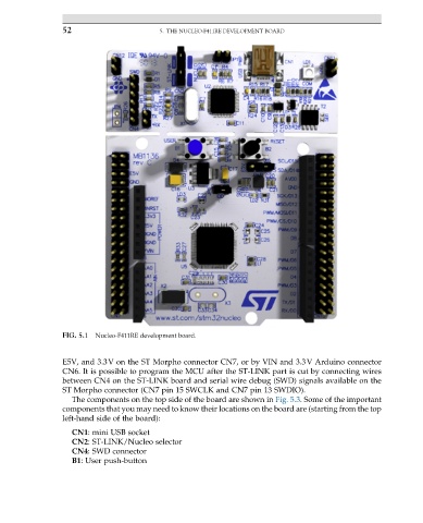
FIG. 5.1 Nucleo-F411RE development board.
E5V, and 3.3V on the ST Morpho connector CN7, or by VIN and 3.3V Arduino connector
CN6. It is possible to program the MCU after the ST-LINK part is cut by connecting wires
between CN4 on the ST-LINK board and serial wire debug (SWD) signals available on the
ST Morpho connector (CN7 pin 15 SWCLK and CN7 pin 13 SWDIO).
The components on the top side of the board are shown in Fig. 5.3. Some of the important
components that you may need to know their locations on the board are (starting from the top
left-hand side of the board):
CN1: mini USB socket
CN2: ST-LINK/Nucleo selector
CN4: SWD connector
B1: User push-button