
Page 93 - Accounting Information Systems
P. 93
64 PART I Overview of Accounting Information Systems
FI G U R E
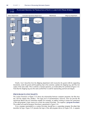
FLOWCHART SHOWING THE TRANSLATION OF FACTS 1, 2, AND 3 INTO VISUAL SYMBOLS
2-22
Sales Department Computer Operations Department Warehouse Shipping Department
Customer Edit and
Credit
Credit History
Check
File
Customer
Order
Sales
Input Order Orders
AR File
Customer Update
Order
Program
Inventory
Finally, Fact 6 describes how the shipping department clerk reconciles the goods with the supporting
documents, sends the goods and the packing slip to the customer, updates the shipping log, and files two
copies of the sales order. This is entirely a manual operation, as evidenced by the symbols in Figure 2-23.
Note that the shipping log uses the same symbol that is used for representing journals and ledgers.
PROGRAM FLOWCHARTS
The system flowchart in Figure 2-23 shows the relationship between computer programs, the files they
use, and the outputs they produce. This high level of documentation, however, does not provide the
operational details that are sometimes needed. For example, an auditor wishing to assess the correctness
of the edit program’s logic cannot do so from the system flowchart. This requires a program flowchart.
The symbol set used for program flowcharts is presented in Figure 2-24.
Every program represented in a system flowchart should have a supporting program flowchart that
describes its logic. Figure 2-25 presents the logic of the edit program shown in Figure 2-26. A separate