
Page 301 - Acquisition and Processing of Marine Seismic Data
P. 301
292 5. PREPROCESSING
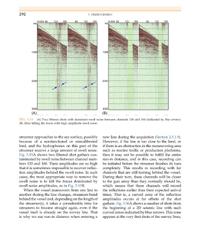
FIG. 5.55 (A) Two filtered shots with dominant swell noise between channels 130 and 160 (indicated by blue arrows).
(B) After killing the traces with high amplitude swell noise.
streamer approaches to the sea surface, possibly new line during the acquisition (Section 2.5.1.9).
because of a nonfunctional or miscalibrated However, if the line is too close to the land, or
bird, and the hydrophones on this part of the if there is an obstruction in the maneuvering area
streamer receive a large amount of swell noise. such as marine traffic or production platforms,
Fig. 5.55A shows two filtered shot gathers con- then it may not be possible to fulfill the entire
taminated by swell noise between channel num- run-in distance, and in this case, recording can
bers 130 and 160. Their amplitudes are so high be initiated before the streamer finishes its turn
that it is sometimes impossible to recover reflec- completely. This results in recording with far
tion amplitudes behind the swell noise. In such channels that are still turning behind the vessel.
cases, the most appropriate way to remove the During their turn, these channels will be closer
swell noise is to kill the traces dominated by to the gun array than they normally should be,
swell noise amplitudes, as in Fig. 5.55B. which means that these channels will record
When the vessel maneuvers from one line to the reflections earlier than their expected arrival
another during the line changes, streamers bend times. That is, a curved zone of the reflection
behind the vessel and, depending on the length of amplitudes occurs at far offsets of the shot
the streamer(s), it takes a considerable time for gathers. Fig. 5.56A shows a number of shots from
streamers to become straight again, even if the the beginning of a 2D seismic line with such
vessel itself is already on the survey line. That curved zones indicated by blue arrows. This zone
is why we use run-in distance when entering a appears at the very first shots of the survey lines,