
Page 31 - Acquisition and Processing of Marine Seismic Data
P. 31
22 1. INTRODUCTION
FIG. 1.14 (A) A single-channel seismic section, and (B) a 48-fold stacked multichannel seismic section collected along the
same 2D survey line.
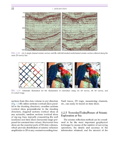
FIG. 1.15 Schematic illustration for the illumination of subsurface using (A) 2D survey, (B) 3D survey, and
(C) actual image.
sections from this data volume in any direction Fault traces, 2D traps, meandering channels,
(Fig. 1.16B): inline sections (vertical slices paral- etc., can easily be traced on time slices.
lel to the shooting direction), crossline sections
(vertical slices perpendicular to the shooting
direction), diagonal sections (vertical slices at 1.2.5 Yesterday/Today/Future of Seismic
any azimuth), random sections (vertical slices Exploration at Sea
of zig-zag lines, typically crosscutting the well
locations) and time slices (horizontal maps pre- The seismic reflection method can be consid-
pared for constant time values). Horizontal time ered to be the most important geophysical
slices are the essential parts of 3D data volumes, technique by means of the number of surveying
which provide distribution of seismic reflection operations, the details and accuracy in the
amplitudes in 2D at any constant recording time. information obtained, and the amount of the