
Page 28 - Acquisition and Processing of Marine Seismic Data
P. 28
1.2 MARINE ACOUSTIC METHODS 19
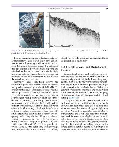
FIG. 1.12 (A) A 3.5 kHz Chirp transducer array ready for an over-the-side mounting; (B) an example Chirp record. The
penetration of Chirp data is approximately 50 m.
Boomers generate an acoustic signal between signal has no side lobes and does not oscillate,
approximately 1 and 6 kHz. They have capaci- its resolution is quite high.
tors to store the energy until shooting, and at
each shot point, the stored energy is discharged 1.2.4 Single Channel and Multichannel
through a spiral coil, which flexes a copper plate Seismics
attached to the coil to produce a stable high-
frequency seismic signal. Boomer sources are Conventional single- and multichannel seis-
mounted either on a catamaran towed behind mic methods utilize much higher amplitude
the vessel, or on a tow-fish. acoustic signals at relatively lower frequency
Normally, large transducer arrays are bands. Therefore, they have much more penetra-
required to produce a narrow beam in subbot- tion depth than subbottom profilers, although
tom profiler frequency bands of 1–10 kHz. To their resolution is relatively lower. Today, the
overcome this issue, nonlinear acoustic systems, conventional seismic method is the primary tool
termed parametric systems, are used. Paramet- for offshore hydrocarbon exploration, mapping
ric systems enable us to produce a narrow of shallow and deep stratigraphy, and structural
source signal using relatively small-size trans- setting (Table 1.6).
ducers. In parametric sounding, two different If we put a receiver next to the seismic source
high-frequency acoustic signals (f 1 and f 2 ), called and start recording at that receiver after each
primary frequencies, are emitted into the water shot, we can obtain true zero-offset seismic data
column simultaneously. Nonlinear interference when we move this system along a straight sur-
of these two signals produces a third one with vey line. Acquisition geometry very similar to
a new frequency band, called a secondary fre- this configuration is still used in marine explora-
quency, which equals the difference between tion and is known as single-channel seismic
primary frequencies (f 3 ¼jf 1 f 2 j). For instance, reflection. As its name indicates, seismic data
using a primary frequency pair of 100 and is collected using a very short streamer consist-
104 kHz or 100 and 112 kHz, it is possible to ing of only one single recording channel and a
obtain 4 and 12 kHz secondary frequency sig- single-channel seismic recorder. Although it is
nals, respectively. Since a narrow secondary supposed to be zero-offset acquisition, there is