
Page 36 - Acquisition and Processing of Marine Seismic Data
P. 36
1.3 FUNDAMENTALS OF MARINE SEISMICS 27
direction parallel to the ray path that the wave waves, they are not observed in marine seismic
propagates on (Fig. 1.17), but it changes into pro- data since S waves in marine seismic surveys are
grade motion at some depth (e.g., Sheriff and nonexistent.
Geldart, 1995). The Rayleigh waves produce a
well-known noise type, termed ground roll in 1.3.2 Reflection From an Interface
land seismics.
P waves are the major seismic wave type used When the compressional wave strikes an
in seismic exploration both in land and marine interface separating two media with different
seismic acquisition. According to Eq. (1.3), S propagation velocities and densities, some cer-
wave velocity depends on rigidity modulus tain part of the incident energy is reflected from
and the density of the propagating medium. the boundary back into the upper medium,
Since rigidity is zero in liquids, S waves do not while the remaining part is transmitted into
propagate in water, and therefore explorations the underlying media (Fig. 1.18A). A reflecting
by S waves are not common in marine seismics. interface in seismic methods is determined by
However, it is possible to record S waves using the differences in velocity and density values
ocean bottom cables (OBCs), ocean bottom seis- of both layers it separates. Seismic waves
mometers (OBSs), or seabed nodes in marine are reflected from the interfaces that separate
surveys, which can provide four-component two media of different acoustic impedances
(4C) seismic data (Section 2.4.1). Although still defined by
not common, S wave surveys in marine explora-
Z ¼ ρV (1.4)
tion can also be done by using converted wave
surveys, in which S waves converted from P where Z is the acoustic impedance, ρ is density,
waves at the reflecting interfaces by phase con- and V is velocity of the medium.
version are recorded and specifically processed If the incidence angle is not 90 degrees, which
to obtain converted S wave seismic sections, is the case for nonnormal incidence, reflected
which are then interpreted along with the regu- and transmitted SV waves are also generated
lar P wave sections. Because the surface waves from incident P waves, which is known as phase
are considered to be a combination of P and S conversion. In case of nonnormal incidence, the
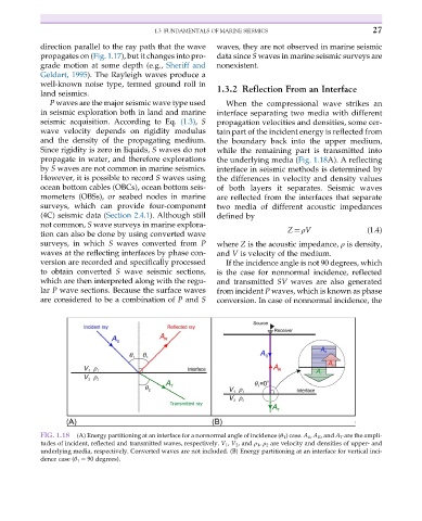
FIG. 1.18 (A) Energy partitioning at an interface for a nonnormal angle of incidence (θ 1 ) case. A 0 , A R , and A T are the ampli-
tudes of incident, reflected and transmitted waves, respectively. V 1 , V 2 , and ρ 1 , ρ 2 are velocity and densities of upper- and
underlying media, respectively. Converted waves are not included. (B) Energy partitioning at an interface for vertical inci-
dence case (θ 1 ¼ 90 degrees).