
Page 38 - Acquisition and Processing of Marine Seismic Data
P. 38
1.3 FUNDAMENTALS OF MARINE SEISMICS 29
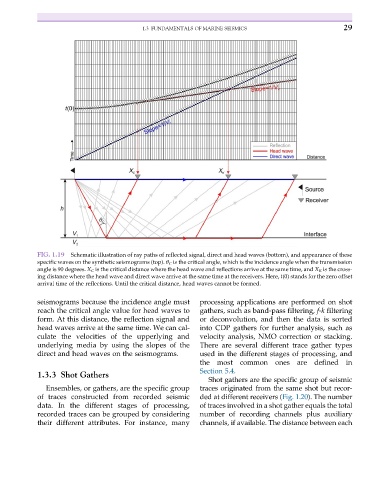
FIG. 1.19 Schematic illustration of ray paths of reflected signal, direct and head waves (bottom), and appearance of these
specific waves on the synthetic seismograms (top). θ C is the critical angle, which is the incidence angle when the transmission
angle is 90 degrees. X C is the critical distance where the head wave and reflections arrive at the same time, and X K is the cross-
ing distance where the head wave and direct wave arrive at the same time at the receivers. Here, t(0) stands for the zero offset
arrival time of the reflections. Until the critical distance, head waves cannot be formed.
seismograms because the incidence angle must processing applications are performed on shot
reach the critical angle value for head waves to gathers, such as band-pass filtering, f-k filtering
form. At this distance, the reflection signal and or deconvolution, and then the data is sorted
head waves arrive at the same time. We can cal- into CDP gathers for further analysis, such as
culate the velocities of the upperlying and velocity analysis, NMO correction or stacking.
underlying media by using the slopes of the There are several different trace gather types
direct and head waves on the seismograms. used in the different stages of processing, and
the most common ones are defined in
Section 5.4.
1.3.3 Shot Gathers
Shot gathers are the specific group of seismic
Ensembles, or gathers, are the specific group traces originated from the same shot but recor-
of traces constructed from recorded seismic ded at different receivers (Fig. 1.20). The number
data. In the different stages of processing, of traces involved in a shot gather equals the total
recorded traces can be grouped by considering number of recording channels plus auxiliary
their different attributes. For instance, many channels, if available. The distance between each