
Page 41 - Acquisition and Processing of Marine Seismic Data
P. 41
32 1. INTRODUCTION
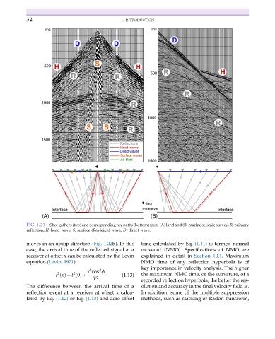
FIG. 1.21 Shot gathers (top) and corresponding ray paths (bottom) from (A) land and (B) marine seismic survey. R, primary
reflection; H, head wave; S, surface (Rayleigh) wave; D, direct wave.
moves in an updip direction (Fig. 1.22B). In this time calculated by Eq. (1.11) is termed normal
case, the arrival time of the reflected signal at a moveout (NMO). Specifications of NMO are
receiver at offset x can be calculated by the Levin explained in detail in Section 10.1. Maximum
equation (Levin, 1971) NMO time of any reflection hyperbola is of
key importance in velocity analysis. The higher
x cos ϕ
2
2
2
2
t xðÞ ¼ t 0ðÞ + (1.13) the maximum NMO time, or the curvature, of a
V 2
recorded reflection hyperbola, the better the res-
The difference between the arrival time of a olution and accuracy in the final velocity field is.
reflection event at a receiver at offset x calcu- In addition, some of the multiple suppression
lated by Eq. (1.12) or Eq. (1.13) and zero-offset methods, such as stacking or Radon transform,