
Page 71 - Acquisition and Processing of Marine Seismic Data
P. 71
62 2. MARINE SEISMIC DATA ACQUISITION
scale propeller at the bottom. The front end of 2.1.9 Lead-in and Deck Cables
each streamer is located with a specific buoy
termed a dilt float or front buoy (Fig. 2.18D). Streamers are coupled to the seismic vessels
In some dilt float models, the depth of the by strong lead-in cables, which are used to
streamer can be arranged with an adjustable deploy the streamers from the vessel and to
steel cable. Both tail buoys and dilt floats are maintain the tow distance of the streamers from
the stern of the vessel. Lead-in cables connect the
made from polyethylene material.
front end of the streamer to the deck cable via a
The lateral distance between the streamers is
fixed by deploying a specific cable called a slip-ring mounted on the axial part of the
spreader or super wide cable. There is only one streamer reel (Fig. 2.20A). It includes electrical
spreader cable in 2D vessels, while two identical or optical conductors that transmit the seismic
spreader cables are used in 3D surveys, one for and other streamer data from the sensors on
each side of the vessel (Fig. 2.3). Spreader cable the streamers. The signal is transmitted from
is dragged from the vessel by paravanes at both lead-in to streamer interface unit located in the
instrument room, via a specific cable known as
sides of the vessel, which provide correct tension
the deck cable (Fig. 2.20A). Signal transmission
to the spreader cables to extend from the vessel
wires within the lead-in cable are surrounded
during the deployment. A paravane includes a
by several layers of helically wound steel wires,
cylindrical float and a frame with deflectors
termed armor, to protect the conductors. Lead-
attached to the float, and is generally suspended
in cables are usually deployed with cable fairing,
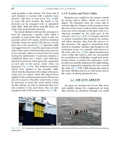
at each side of the survey vessel when not
which is required to streamline the flow around
deployed (Fig. 2.19A). The deflectors produce
the cable (Fig. 2.20B). Cable fairing also reduces
lateral force applied to the spreader cable,
the cable vibration, known as cable strum, due to
which directly depends on the shape of the para-
vanes and tow speed. Since the lateral forces the vortex shedding during the tow.
applied to the outermost paravane in 3D surveys
may be excessive when the vessel turns, it may 2.2 AIR GUN ARRAYS
be necessary to lower the vessel speed during
the line change. In order to determine the accu- Air guns are mechanical devices that store
rate position of the paravanes, they are also and rapidly release the compressed air from
equipped with rGPS transponders (Fig. 2.19B). their internal air chambers through four small
FIG. 2.19 (A) A paravane suspended at the port side of the survey vessel when it is at the dock, and (B) a paravane during
deployment.