
Page 72 - Acquisition and Processing of Marine Seismic Data
P. 72
2.2 AIR GUN ARRAYS 63
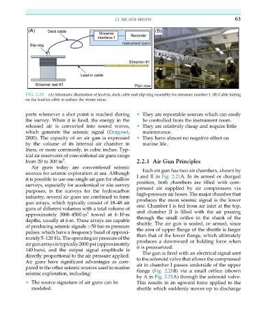
FIG. 2.20 (A) Schematic illustration of lead-in, deck cable and slip-ring assembly for streamer number 1. (B) Cable fairing
on the lead-in cable to reduce the strum noise.
ports whenever a shot point is reached during • They are repeatable sources which can easily
the survey. When it is fired, the energy in the be controlled from the instrument room.
released air is converted into sound waves, • They are relatively cheap and require little
which generate the seismic signal (Dragoset, maintenance.
2000). The capacity of an air gun is expressed • They have almost no negative effect on
by the volume of its internal air chamber in marine life.
liters, or more commonly, in cubic inches. Typ-
ical air reservoirs of conventional air guns range
3
from 20 to 300 in . 2.2.1 Air Gun Principles
Air guns today are conventional seismic
Each air gun has two air chambers, shown by
sources for seismic exploration at sea. Although
I and II in Fig. 2.21A. In its armed or charged
it is possible to use one single air gun for shallow
position, both chambers are filled with com-
surveys, especially for academical or site survey
pressed air supplied by air compressors via
purposes, in the surveys for the hydrocarbon
high-pressure air hoses. The major chamber that
industry, several air guns are combined to form produces the main seismic signal is the lower
gun arrays, which typically consist of 18–48 air one. Chamber I is fed from air inlet at the top,
guns of different volumes with a total volume of and chamber II is filled with the air passing
3
approximately 3000–4500 in towed at 4–10 m through the small orifice in the shank of the
depths, usually at 6 m. These arrays are capable shuttle. The air gun is sealed, or armed, since
of producing seismic signals >50 bar-m pressure
the area of upper flange of the shuttle is larger
pulses, which have a frequency band of approxi-
than that of the lower flange, which ultimately
mately5–120 Hz.Theoperatingairpressureofthe
produces a downward or holding force when
airgunarraysistypically2000 psi(approximately
it is pressurized.
140 bars), and the output signal amplitude is
The gun is fired with an electrical signal sent
directly proportional to the air pressure applied.
Air guns have significant advantages as com- to the solenoid valve that allows the compressed
pared to the other seismic sources used in marine air in chamber I passes underside of the upper
seismic exploration, including: flange (Fig. 2.21B) via a small orifice (shown
by A in Fig. 2.21A) through the solenoid valve.
• The source signature of air guns can be This results in an upward force applied to the
modeled. shuttle which suddenly moves up to discharge