
Page 81 - Acquisition and Processing of Marine Seismic Data
P. 81
72 2. MARINE SEISMIC DATA ACQUISITION
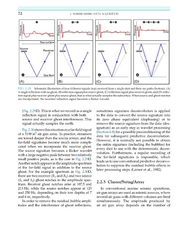
FIG. 2.29 Schematic illustration of four different signals (top) received from a single shot and their ray paths (bottom). (A)
A single reflection with no ghost, (B) reflection signal plus source ghost, (C) reflection signal plus receiver ghost, and (D) reflec-
tion signal plus receiver ghost plus source ghost, that is what actually samples the subsurface. When source and ghost notches
are incorporated, the recorded reflection signal becomes a Ricker wavelet.
(Fig. 2.29D). This is what we record as a single sometimes signature deconvolution is applied
reflection signal in conjunction with both to the data to convert the source signature into
source and receiver ghost interferences. This its zero phase equivalent (dephasing) or to
signal actually samples the earth. remove the source signature from the data (des-
ignature) as an early step in wavelet processing
Fig.2.30showsthissituationonafar-fieldsignal
3
of a 3190 in air gun array. In practice, streamers (Section 6.8) for a possible preconditioning of the
data for subsequent predictive deconvolution.
aretowed deeper than thesourcearrays, andthe
However, it is normally not possible to obtain
far-field signatures become much more compli-
the entire signature (including the bubbles) for
cated when we incorporate the receiver ghost:
every shot to use with the deterministic decon-
The source signature becomes a Ricker wavelet
volution. Furthermore, a regular recording of
with a large negative peak between two relatively
the far-field signatures is impossible, which
small positive peaks, as is the case in Fig. 2.29D.
leads us to use conventional predictive deconvo-
Another notch appears in the amplitude spectrum
lution to suppress the residual bubble effects in
of the far-field signal in addition to the source
later processing steps (Larner et al., 1982).
ghost. For the example spectrum in Fig. 2.30D,
there are two receiver (R 1 and R 2 )and twosource
(S 1 and S 2 ) ghost notches in the amplitude spec- 2.2.5 Cluster/String/Array
trum. Receiver ghost notches arise at 107.5 and
215 Hz, while the source notches appear at 125 In conventional marine seismic operations,
and 250 Hz, depending on their tow depths of 7 air gun arrays are used as seismic sources, where
and 6 m, respectively. several air guns with different volumes are fired
In order to remove the residual bubble ampli- simultaneously. The amplitude produced by
tudes and the interference of ghost reflections, an air gun array depends on the number of