
Page 88 - Acquisition and Processing of Marine Seismic Data
P. 88
2.2 AIR GUN ARRAYS 79
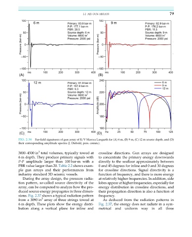
FIG. 2.36 Far-field signatures of gun array of R/V Marcus Langseth for (A) 6 m, (B) 9 m, (C) 12 m source depth, and (D)
their corresponding amplitude spectra (J. Diebold, pers. comm.).
3
3000–4500 in total volumes, typically towed at crossline directions. Gun arrays are designed
6 m depth. They produce primary signals with to concentrate the primary energy downwards
P-P amplitude larger than 100 bar-m with a directly to the seafloor approximately between
PBR value larger than 20. Table 2.2 shows exam- 0 and 45 degrees for inline and 0 and 30 degrees
ple gun arrays and their performances from for crossline directions. Signal directivity is a
industry standard 3D seismic vessels. function of frequency, and there is more energy
During the array design, the pressure radia- at relatively higher frequencies. In addition, side
tion pattern, so-called source directivity of the lobes appear at higher frequencies, especially for
array, can be computed to analyze how the pro- energy distribution in crossline directions, and
duced source energy propagates in three dimen- their propagation direction is also a function of
sions. Fig. 2.37 shows a typical radiation pattern frequency.
3
from a 3090 in array of three strings towed at As deduced from the radiation patterns in
6 m depth. These plots show the energy distri- Fig. 2.37, the energy does not radiate in a sym-
bution along a vertical plane for inline and metrical and uniform way in all three